On the Modeling of Round Bilge Hulls
C-spline Lofted Surface and the vertex curve method
by Reinhard Siegel
Introduction
This article shows on the basis of the model sy15.ms2 by what considerations the author creates a round bilge hull in MultiSurf. This is not about making a hull with specific dimensions or shape features. But it comes to show which method is practical, so in the end it is on the screen what you imagine.
Abbreviations used:
cp: control point (support point)
mc: master curve = support curve
In the following the terms used for point, curve and surface types are those of MultiSurf. This may serve the understanding and traceability.
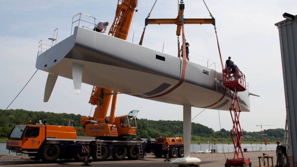
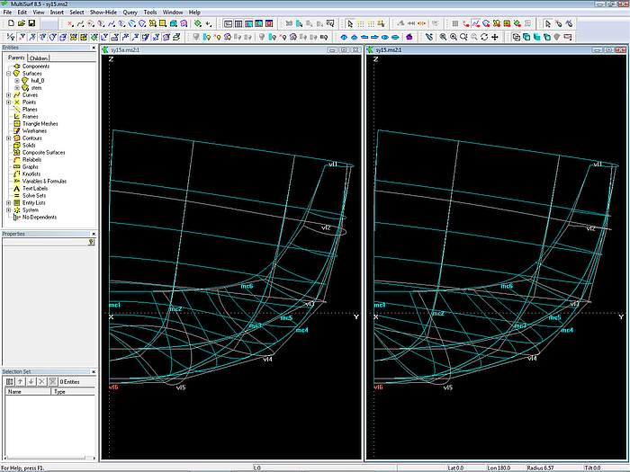
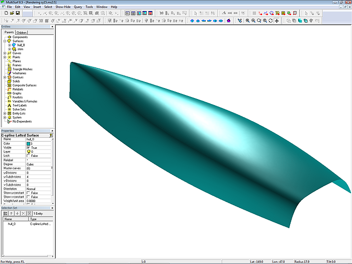
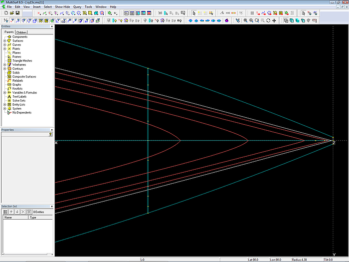
Model sy15.ms2 opened in MultiSurf. Note the arrangement of managers and toolbars to provide a wide drawing area.
When the model opens, hull outline, stations, waterlines and buttocks are displayed.
The surface type of the hull is a C-spline Lofted Surface.
Why C-spline Lofted Surface?
The shape of the boat suggests it: there is no rapid change of curvature in longitudinal direction, no discontinuities. A C-spline Lofted Surface is analogous to carvel, clinker or strip-planking construction: master curves (support curves) are „planked“ with C-spline Curves (cubic splines). A C-spline Curve is a mathematical model of a spline or batten.
Note: if the hull shape leans to planking ⇒ C-spline Lofted Surface
Further, a C-spline Lofted Surface interpolates its supporting master curves (mcs). The "planking battens“ are fastened directly to the mcs. Therefore they are part of the hull surface, they lie in the surface and not somewhat off it. Thus there is a direct relation between the shape of the mcs and the shape of the hull – the form of the mc is the hull form at its location.
Note: if the mcs should lie in the hull surface ⇒ C-spline Lofted Surface
The hull surface is supported by 6 Master curves.
Why 6 mcs?
And not 3 or 4? The number of mcs depends on how many points you need to support a batten to form either the intended hull top edge or the bottom edge of the hull surface (profile, fairbody curve). The less mcs, the less is the local control of the shape, and the more you have to accept what the batten will do. Experience shows that a good compromise between simplicity (few mcs) and local influence is 6 mcs.
Note: the most complicated boundary curve (sheer, profile) determines the number of mcs and their position in the longitudinal direction.
Often, the profile is more complex in shape than the sheer due to the required position of the center of buoyancy.
6 mcs is not a dogma. When you achieve the desired shape of sheer and profile with fewer mcs, take less. If 6 mcs will not work, try it with 7 mcs or 8 ...
The mcs of the hull surface are B-spline Curves.
Why B-spline Curve as support curve?
A B-spline Curve is easy to shape with few control points (cps). It does not oscillate between its control points. It always starts tangent to the line between 1st and 2nd cp and ends tangent to the line between the second last and last cp. This tangency property is very useful for the construction of a fair transition between 2 curves or between 2 surfaces.
All B-spline Curves have the same degree and the same number of cps.
Why same degree and same number of cps?
The mcs are "planked" with C-spline Curves – that is just the C-spline Lofted Surface. The planking process is like this: a C-spline Curve is passed through the first point of each mc, making the sheer of the hull. Then, another point is calculated on each mc, a little bit below the previous one, and the next C-spline Curve is sprung through those points. This procedures is continued until the last curve passes through the end point of all mcs (profile of hull). In other words, a batten moves from top to bottom along the mcs (always in contact) and so sweeps out a surface in space.
The "strip planks" of a C-spline Lofted Surface correspond to the u-constant parameter curves of the surface.
Consider a real carvel or clinker built hull – all planks run in a nice sweep from bow to stern. Thus, in order to create a fair C-spline Lofted Surface without unintended irregularities, the „planks“ (u-constant parameter curves ) should also run in a harmonious fashion. However, this requires, that the sequence of curve points on the mcs is harmoniously distributed along them. For the curve type B-spline Curve this holds true only with the same degree and the same number of cps.
Why 6 cps?
The more cps, the greater the local control of the curve shape. On the other hand, the more work is required to position the cps to achieve the desired form as well as fairness (no discordant curvature distribution). Experience shows that 6 cps are a good compromise between simplicity (few control points) and local influence.
6 cps is not a dogma. If you achieve the desired form of the mcs with fewer points, take less. Will 6 cps not work for your hull, try it with 7, 8 ...
Note: the most complicated mc determines the number of cps of all mcs.
Why do mcs run in cross section planes?
If a mc runs in a cross section plane, then the shape of the mc is simultaneously the shape of a station at the mc location. Thus in X-view the mc will show the true hull shape, so we have a direct relation between the display on the screen and the hull form: what you see is what you get.
Mcs in cross section planes are not a dogma. In highly curved hull areas like the bow of a powerboat or a canoe stern, oblique mcs work well. But where there is no such need, I prefer mcs in cross section planes.
All the corresponding cps of the mcs are connected with C-spline Curves as vertex curves.
Why vertex curves?
The task is not only to model a surface of desired size and shape, the surface must also be fair, smooth, without unintended irregularities. Similar to a clinker, carvel or strip-plank build real hull with its fair running planks a C-spline Lofted Surface is fair if its u-constant parameter curves (its "planks") are fair.
If all mcs are B-spline Curves of the same degree, and if they all have the same number of cps, then the run of the u-constant curves of a C-spline Lofted Surface is closely related to the run of these vertex curves. They visualize how the position of cps develops from the bow towards the stern. If the vertex curves run in a harmonious fashion, the surface is fair.
Note: fair u-constant curves indicate a fair surface.
For a C-spline Lofted Surface the shape of its u-constant curves is closely related to the run of the vertex curves.
The Vertex Curve Method:
provided the mcs are of the same curve type and same degree and have the same no. of cps:
- Fair vertex curves make fair u-constant curves.
- Fair u-constant curves make a fair surface.
- Fair vertex curves make a fair surface.
Thus vertex curves are guiding curves for fairing a C-spline Lofted Surface. If we make them run in a harmonious, regular fashion, the surface is fair.
The requirement for the Vertex Curve Method - all mcs must have the same number of cps - enforces, that the most complicated mc determines the necessary number of cps. Although other mcs of the hull might be shaped with fewer points, we must take the higher number.
This disadvantage is more than offset by the ability of the Vertex Curve Method to control quickly, easily and visually understandable the fairness of the C-spline Lofted Surface.
The task is twofold – position the cps of all mcs to get the intended hull shape and – at the same time – achieve smooth vertex curves.
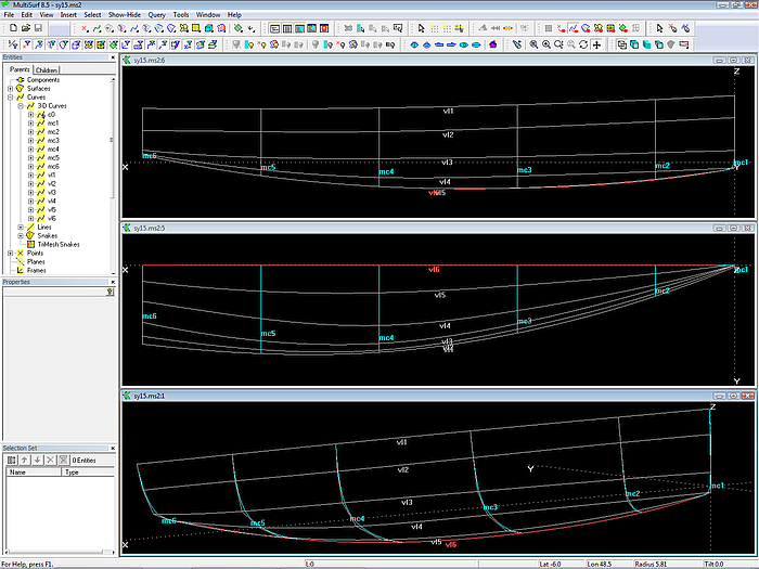
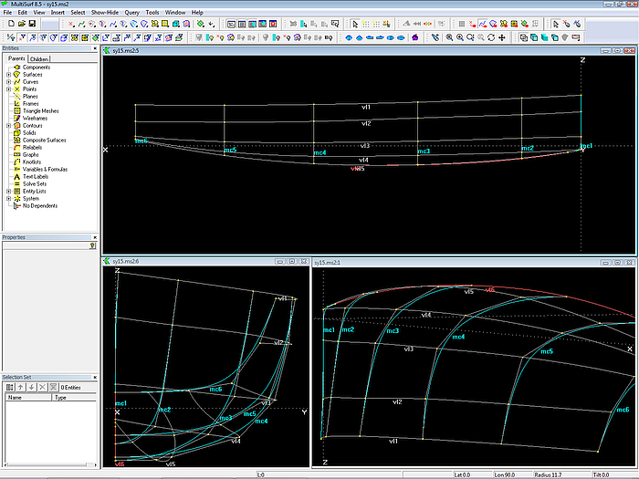
Vertex curves as guiding curves for fairing.
It is important to note, that unregular u-constant curves are not inevitably a sign of unfairness. Imagine a smooth white painted hull, onto which longitudinal curves are drawn with a black pen. They may look ever so crooked, but the hull remains fair.
Note: if u-constant curves are unfair, the surface can be fair nevertheless.
However, the modeling of hulls by the Vertex Curve Method is much more straightforward and faster than the attempt to make regular u-constant curves from unsimilar mcs (different in type, degree, no. of cps) by relabeling or permanent checking with irregular u-constant curves if the surface is fair in spite of it.
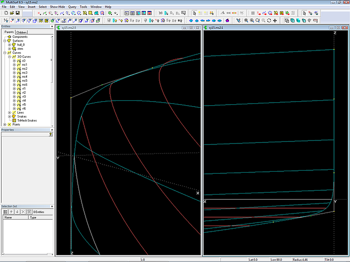
C-spline Curve vertex curve vl1 passes through cp 1 of each mc. It is identical to the top edge of the hull surface. Vertex curve vl6 connects all cps 6. It is identical to the bottom edge of the hull.
Why fairing in 3D view?
The hull surface must be fair. The Vertex Curve Method states: fair vertex curves make a fair surface. Thus the cps of the mcs must be arranged to make the vertex curves run smooth. This can be very well controlled by looking along the vertex curves in 3D view. One can rotate the model on the screen around any point and view obliquely look along any curve. Just as if one had built a real model and it would turn in his hand back and forth. This way one can see any irregularity in the run of a curve, a waterline, etc.
In Y-view the bump in vl2 near mc2 is hard to see. However, in 3D-view the unfairness of curves is easy to detect. Vertex curve vl4 does not run similar to vl3 and vl5.
Why restricting the dragging of cps?
Moving a point in 3D view will usually change each of its 3 coordinates. This can be prevented by using the property Dragging of the Point entity.
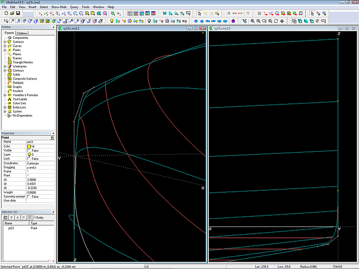
For example, to ensure that all cps of mc2 to mc6 stay in their cross section planes, their Dragging property is set to (y and z). Now, when you move these points in 3D view, their x-coordinates do not change.
mc4, mc5 and mc6 should end normal (perpendicular) to the centerplane. This property is hardwired by making the last but one cp (here cp 5) relative to the last cp, with dz = 0. In order to maintain this relation through all editing, its dragging is set to (y). So you can just slide point cp 5 back and forth, but not up and down. Its reference point cp 6 is made movable in z only, since it must stay on centerplane.
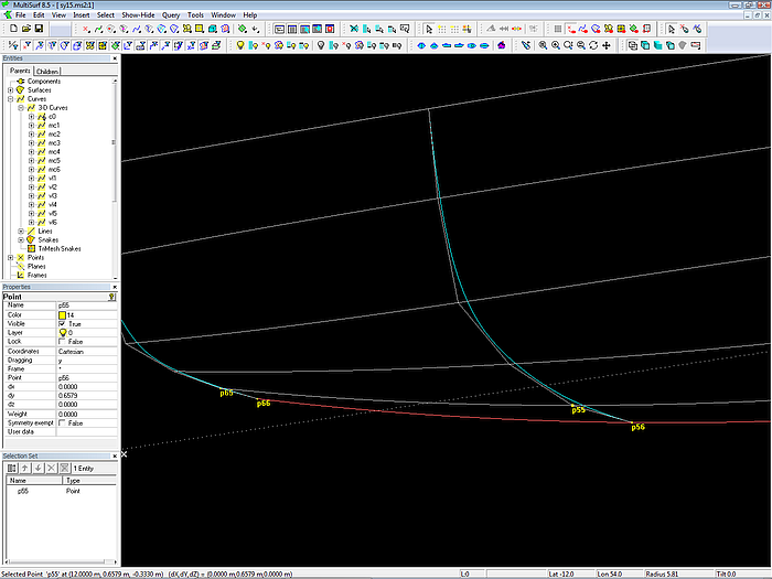
Points p55 and p65 are relative to points p56 and p66. If dragging of p56 and p66 is set to (z) and dragging of p55 and p65 is set to (y) the points can be moved in 3D view while keeping the required relation ( mcs end normal to centerplane).
Why do so and not otherwise?
Instead making cp 5 of the last 3 mcs relative to cp 6, one could make cp 6 as a Projected Point on the centerplane. Then the cps 5 and 6 would also have always equal z-coordinates, and thus the B-spline mcs would end exactly normal to the centerplane.
Suppose we do it like this. And we set the dragging of cp 5 to (y and z). Now we want to move this point a bit away from the centerplane, i.e. change its y but keeping z. So we set its dragging to (y). But if we need later some change to z while keeping y, we must change the dragging again. So there will be a continuous editing of the dragging setting if we do not want to change both coordinates when moving the point in 3D view. This is just plain awkward.
Why should you pay attention to the run of vl5 and vl6?
From mc4 on the aft mcs end normal to the centerplane, their cps 5 and 6 have the same z-coordinates. So at these mc locations vl5 and 6 run on top of each other in Y-view. But also between the mcs both vertex curves must be superimposed in Y-view. Otherwise it may cause a positive or negative rise of floor, that is, the hull surface does not terminate normal to the centerplane. Therefore one must take care that from mc4 on both vl5 and vl6 are superimposed in Y-view.
How to do that?
Select cp 5 of mc3 (name: „p35“), then select the Y-view and zoom deeply into the space between mc4 and mc5. Now check, if vl5 and vl6 coincide, or if vl5 run above or below of vl6. If this is the case, and cp 5 of mc3 is still selected, change its z-coordinate via the Properties manager until both vertex curves coincide. Often we deal with a fraction of a millimeter in the z-coordinate of cp 5 on mc3.
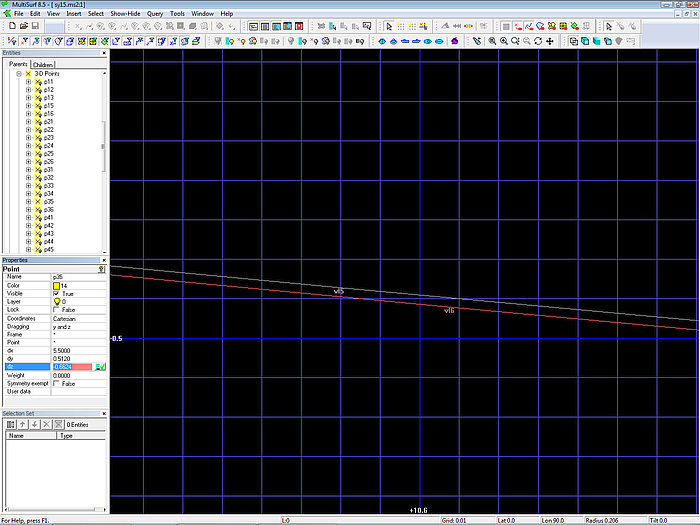
By deep zooming very small differences can be detected and corrected.
Note: use the Properties manager if you want to move a point that is off the screen.
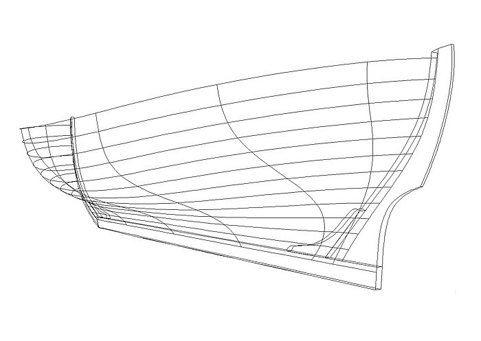
In Render View you can also check whether the surface has a ridge or indentation in the hull aftbody.
Check of rise of floor in the aftbody by Render View.
Why pay attention to the entry of the bow-mc into the profile?
The vl6 describes the contour of the profile. The bow-mc must run without an unintended break into the fairbody. To check that by viewing this spot in 3D is easy. Select cp 6 of mc1, Zoom to Selection to make cp 6 the point of rotation, then zoom deeply in and turn the model until your view slides along the end of mc1 and the begin of vl6.
Break between bow-mc and profile (vl6) can easily detected and corrected in 3D view.
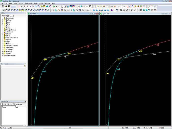
Both curves will meet without a break if the tangent at the end of the bow-mc coincide with the tangent at the begin of the vertex curves vl6.
If there is unfairness, you can remove it manually by shifting cp 5 or cp 6 of mc1 in z-direction until it looks sufficiently smooth for building accuracy.
However, this is by far not a permanent solution. As soon as something is changed to the bow or to the profile, you must manually fix the tangency again.
Here is how to do it better in MultiSurf. Again we make use of the tangency property of B-spline Curves. First, create a line that is tangent to vl6 in its starting point (Line between cp 6 and a Tangent Point based on Bead at t=0 on vl6). Next create a bead on this tangent line and replace with it cp 5 of the bow-mc. With this construction the tangent entry of the bow-mc to the profile of the hull is hardwired into the model.
Note: hardwire required relations
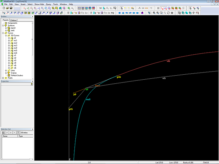
Hardwired permanent tangency between bow and profile by means of MultiSurf.
Why is the last mc beyond the transom?
The hull surface is somewhat longer than the actual boat. That is, there is a transom surface in mind, against which the hull is trimmed. If you put the last mc on the transom surface in order to save the trimming of the hull you should be aware, that the hull surface aft will inevitably change if position, inclination, or shape of the transom surface is modified. Those things are often subject of last minute changes.
You build in independency, if you do it differently. Then the transom surface can be modified, without any change to the hull. Is there a plausible reason why the hull form should change, if you change the slope or the radius or the position of the transom?
Note: Do not build in unnecessary dependencies.
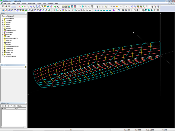
How to eliminate hollow waterlines
With a hull where the stem meets the profile with severe curvature (tight forefoot), the waterlines in the bow area are often hollow. This is not a law of nature in computer-aided ship design.
Hollow waterlines cannot be seen in Z-view (plan view).
A Z-view may not reveal hollow waterlines. Now check the hull entrance in 3D view.
3D viewing is a powerful tool to check the run of curves and contours.
What is the reason for hollow waterlines? As any other hull section the shape of the waterlines results from the run of the u-constant curves of the hull surface. If they rise up towards the stem considerably, hollow waterlines occur. Hulls with a tight forefoot are prone to this.
If hollow waterlines are not intended, the rise of the u-constant curves towards the stem must be reduced.
Hollow waterlines removed by redistribution of the lower cps on bow-mc.
Move the lower cps of the bow-mc a bit aft. So the u-constant curves will run less steep and the waterlines get straight.
Why Entity Lists
In the model there are 3 Entity Lists: edit_hull_0, view_boat_0, view_lines_0. An Entity List contains the names of objects.
Entity Lists are extremely helpful in controlling what appears on the screen. Using Entity Lists a whole set of entities can quickly be selected, shown or hidden. Unlike layers an entity can belong to several lists.
Example - show the content of an Entity List: in the Entities manager, select the wanted list, then main menu/ Show Hide / Show / Parents (or faster: click the toolbar button Show Parents).
The Entity List edit_hull_0 contains only those points, curves etc. which have to do with the modeling of the hull surface.
Why hull_0?, stations_0 ...
Names are very important in MultiSurf. If you know the name of an entity, which is currently not displayed, you can much faster select it via the Entities manager, than finding it via searching along dependency branches of displayed entities.
So catchy names are immense useful and informative. Everyone will develop the proper system for him. The suffix "_0“ in the name hull_0 indicates me: it is the basis surface of the hull, namely the surface, which is made directly from the mcs. If there is a Trimmed Surface or SubSurface as a child, it will be named hull.
Thus stations_0 are cross sections of hull_0, and so on.
So far for the model sy15.ms2. The modeling of a round bilge hull with a full length and vanishing longitudinal chine will be dealt with in following articles.