On Modeling Ship Hull Forms in MultiSurf
by Reinhard Siegel
Introduction
An evident form characteristic of ships, such like cargo vessels, container carriers or cruise liners is, that portions of the hull surface are flat. Many ships also feature a parallel midbody, i. e. a sequence of cross sections is identical. Common to ships is also the bulbous bow. This article deals with methods how to model those hull forms. It is not about designing a hull with specific dimensions and shape, but explains the pros and cons of various methods.
Abbreviations used:
cp: control point (support point)
mc: master curve = support curve
In the following the terms used for point, curve and surface types are those of MultiSurf. This may serve the understanding and traceability.
Form features
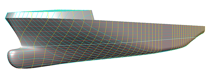
Typical for ship hulls are flat side, flat bottom and parallel midbody. The main cross section shows a quarter of a circle for the turn of bilge, a vertical straight side line and a horizontal or slightly raised line of floor. Towards stem and stern the height of the side flat and the width of the bottom flat decrease. The bow bulb has some kind of counterpart in front of the propeller, aimed to improve the local water flow.
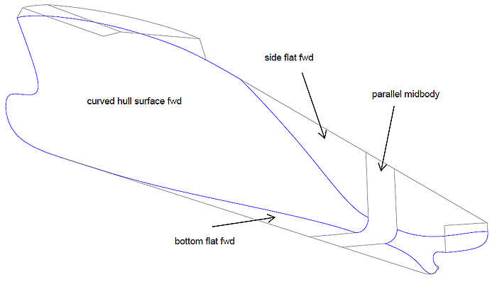
Ship hull form features are curved and flat regions and a parallel midbody.
Thus we can divide the hull surface in flat regions and curved regions. Flat bottom and curved hull are smoothly joint. Also side flat and hull in the underwater area; above water sometimes hull and side meet with a break to increase the space for cargo. Also the curved foreship and aftship region run tangentially into the midbody.
1 Foreship
Cargo vessel forebody
Let us consider first the forebody of a typical cargo vessel. Bulbous bow and tangential entry into side, bottom and midbody are the prerequisites of the curved hull surface. Four surface kinds are nominees:
- B-spline Lofted Surface
- C-spline Lofted Surface
- X-spline Lofted Surface
- B-spline Surface / NURBS Surface
Any kind of lofted surface is generated by the same procedure: on each of the control curves or master curves MultiSurf locates points at the same parameter value t, then uses the resulting series of points as the control points for the lofting curve. Or in other words, the master curves are “planked” by the lofting curves.
B-spline Lofted Surface on B-spline master curves
When we create a B-spline Lofted Surface on B-spline master curves we can use in duplicate respect the tangency property of the B-spline Curve. A B-spline always starts tangent to the first segment and always ends tangent to the last segment of the polyline through its cps. Further, a B-spline is “soft”, easy to free-form with few cps, always close to the polyline through its cps.
If the mcs start vertical and end horizontal, then the entry into side and bottom flat is hard-wired. And if the first mc is on the centerplane and a normal projection of the second mc, the bow will be round along the stem face. And finally, if the second but last mc is a duplicate of the last mc, then the smooth joint with the midbody is established.
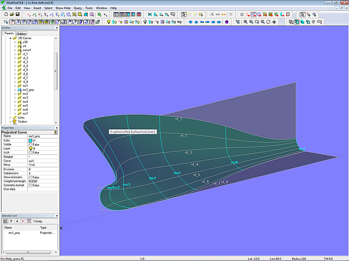
This approach demonstrates model cv-fore-bloft.ms2.
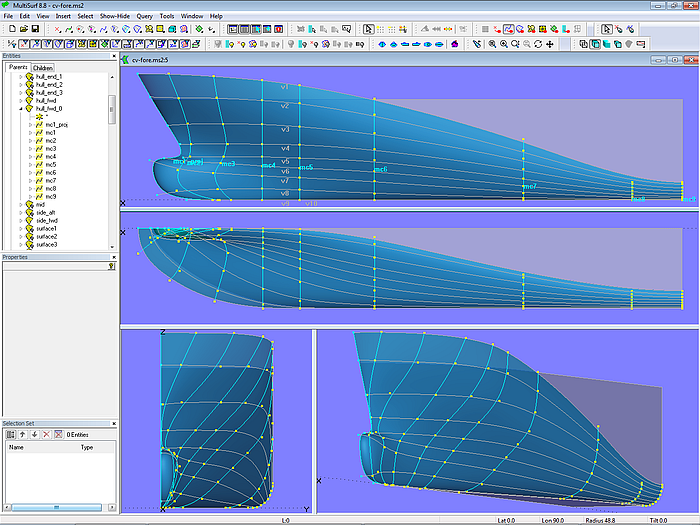
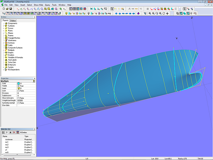
Model cv-fore-bloft.ms2: arrangement of master curves for the basis B-spline Lofted Surface; vertex curves serve as fairing aids.
The model shows 10 B-spline mcs. With the exception of mc2 and mc3 all mcs run in transverse direction. This offers the benefit, that form of mc and form of cross section at its vicinity are closely related.
Besides, if mc3 would run transversely, the unsupported area towards mc2 would be quite large. In order to exercise influence on the shape, especially in regions of rapid change (here: bulbous bow area), the mcs should be arranged in a harmonious fashion - not too close to the preceeding one and not too far away from the following mc.
The cps of mc1 define by their x- and z-coordinate the stem shape in profile view; at the same time they control by their y-coordinate the size of the bow rounding. Projecting mc1 onto the centerplane as Projected Curve mc1_proj guarantees, that the lofting curves (B-spline Curve) all start normal, creating the stem rounding.
On all mcs the second but last cp and the last cp (i. e. cp9 and cp10) has a coordinate z = 0, so they run smoothly into the bottom flat. From mc5 on the y-coordinate of cp1 and cp2 on all mcs is equal to the vessel´s half breadth, so the mcs start vertically.
The tangent joint to the midbody is established by making mc8 and mc9 identical except the x-position; mc8 is a Copy Curve of mc9.
Thus in total 8 mcs of 10 must be modeled interactively. Each is controled by 10 cps, not just a few points, however, the number is caused by the complex shape of the stem.
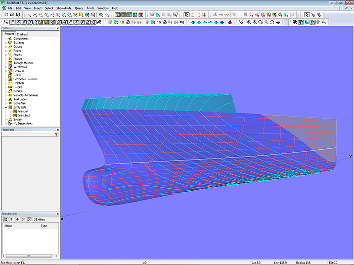
Model cv-fore-bloft.ms2
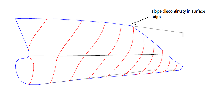
The arrangement of mcs allows the direct definition of the side flat curve (by locating points cp1). At the same time the majority of mcs runs in transverse direction, strengthening the relation between mc shape and cross section shape. In return for this the surface must rise towards the bow above the side of the main deck – a break in the direction of lofting is impossible. Thus this basis surface must be cut off at the deck; creating in that way the discontinuity of the surface edge.
The extension of the basis surface can also be convenient if portions of the hull surface above the main deck are required (forecastle).
B-spline Lofted Surface – alternative mc arrangement
A different arrangement of B-spline mcs is used in model cv-fore-bloft-2.ms2. Here the curved hull surface is not extended above the side flat curve. The rear mc defines both the start of the side flat and the turn of bilge.
Again the second but last mc is identical to the last one, just the x-coordinate of its cps differ. In the example the cps are beads on guiding lines which are parallel to the X axis. The dragging constraint property orf the Point entity might be used as well to keep corresponding cps properly aligned, but those lines and beads are a nice aid visualizing the basic idea.
Also the first mc is the projection of the second mc which defines stem shape and bow round.
Model cv-fore-bloft-2.ms2: arrangement of master curves
Since mcs are not allowed to cross, the mcs forward of the two rear ones must run inclined too - otherwise a wide area of the surface would be unsupported.
This method is quite suitable for free-forming with a few mcs.
C-spline Lofted Surface on B-spline master curves
Except first and last mc a B-spline Lofted Surface does not pass through its inner mcs, it approximates them. There is an indirect relation between shape of mcs and shape of cross sections. On the other hand, a C-spline Lofted Surface passes through all its mcs, it interpolates them. If a mc runs transversely, the surface has exactly its shape at this location. For a surface fitting job the C-spline Lofted Surface is the first choice.
An example is shown in model cv-fore-cloft.ms2.
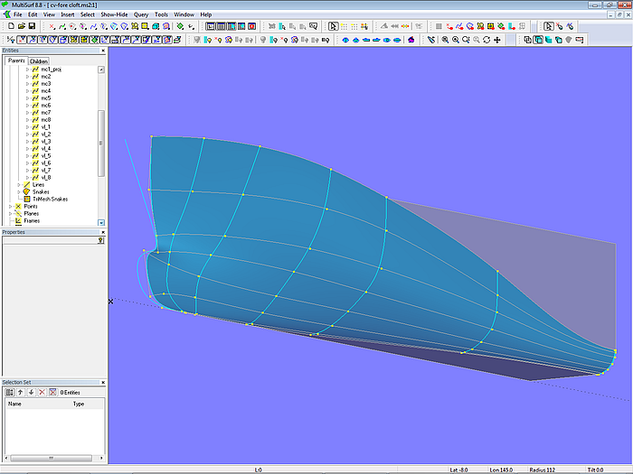
Model cv-fore-cloft.ms2: arrangement of master curves and vertex curves
The basis surface is controled by 8 B-spline master curves, each supported by 8 cps. Vertex curves pass through corresponding cps to help fairing. The tangential entry into the bottom is hard-wired by coordinate z =0 of second but last and last cp on all mcs. From mc5 on all mcs start vertical, i. e. first and second cp has a y-coordinate equal to the half-breadth of the hull.
It is important, that vertex curves 1 and 2 do not swing beyond the side flat of the vessel; the value for the y-coordinate of cp1 and cp2 on mc3 and mc4 must be set carefully.
A C-spline Lofted Surface is a stiff surface, therefore the surface is open at the bow. It must be closed by a bow rounding surface. See herefore the article “On the rounding of bows, sterns...”
To establish the tangential entry of the C-spline Lofted Surface into the parallel midbody the lofting curves are clamped at their t = 1 end by positioning mc7 very close to mc8. Mc7 is a Copy Curve of mc8 and spaced just 0.2 m apart.
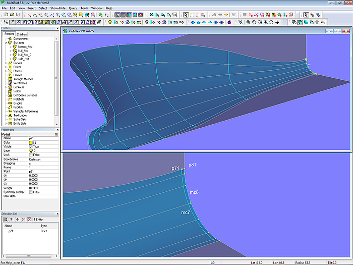
Model cv-fore-cloft.ms2: C-spline Lofted Surface; 2 closely spaced mcs clamp the surface and enforce the tangential entry into the midbody.
Contrary to the B-spline Curve the t-parameter distribution of a C-spline Curve is not effected by the position of its cps. The natural distribution of t is approximately uniform with respect to arc length.
X-spline Lofted Surface
Similar to the C-spline Lofted Surface the X-spline Lofted Surface interpolates its mcs, but in addition offers explicit control over either the slope or the curvature (bending moment) at its v = 0 edge (first mc) and its v = 1 edge (last mc). Model cv-fore-xloft.ms2 shows an example.
Model cv-fore-xloft.ms2: X-spline Lofted Surface with slope continuity to the midbody at its v = 1 edge
Using the X-spline Lofted Surface the tangent joint of the curved hull surface with the parallel midbody is hard-wired in an easy way.
B-spline Surface, NURBS Surface
Given a B-spline Lofted Surface on B-spline master curves of equal degree and same number of cps – as in the example cv-fore-bloft.ms2 discussed above - the identical geometry can be created by a B-spline Surface using just the control points. The creation of the master curves would be saved so, however, it lacks the visual aid of the mcs in the B-spline Lofted Surface version.
A NURBS Surface with the associated weight of all its cps equal to 1 is identical to a B-spline Surface provided corresponding degrees in u- and v-direction are the same. The additional possibility to define weights increases the number of options. Create a curve using 6 cps all of weight = 1 or do it by 3 cps with various weight values? In order to achieve a fair surface not just the cps must be positioned in space in a regular fashion, but also the point weights must be well proportioned. There is opportunity for much fiddeling.
2 Aftship
Likewise to the foreship the curved surface in the aftbody of a ship hull must join tangential to its adjacent neighbours - side and bottom flats and midbody. The methods explained above can be used here accordingly.
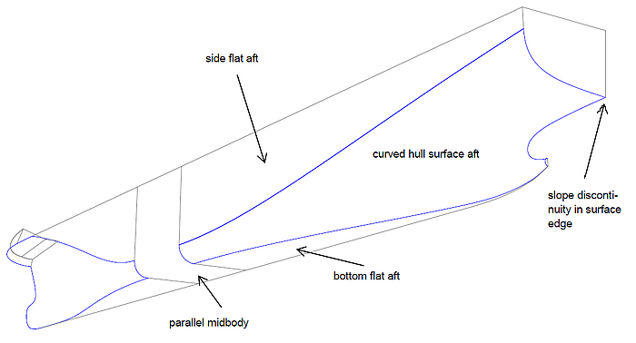
Aftship - curved and flat surfaces
However, there is another break in the aft edge of the hull surface where the transom edge and the stern overhang meets.
B-spline Lofted Surface
Model cv-aft-bloft.ms2 demonstrates an example of a B-spline Lofted Surface on B-spline master curves.
Model cv-aft-bloft.ms2: arrangement of master curves
The surface is supported by 8 B-spline master curves, each one is defined by 8 cps. Vertical start and horizontal end of the mcs is achieved by matching locations of cp1, cp2 and cp8, cp9. Mc7 is a copy of mc8, so the surface will touch the midbody without breaks.
Model cv-aft-bloft.ms2: B-spline Lofted Surface
A portion of mc1, mc2 and mc3 runs on the negative side of the centerplane. Thus the stern overhang is defined indirectly as the intersection of the hull surface and the centerplane. All mcs end at the height of the bottom (z = 0).
Since the side flat curve ends before the transom, the surface must rise above the side of deck.
X-spline Lofted Surface
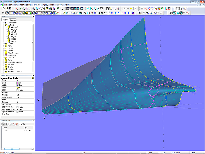
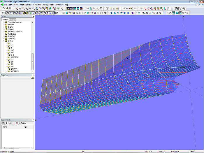
Model cv-aft-xloft.ms2 shows an aftship defined by an X-spline Lofted Surface on B-spline master curves.
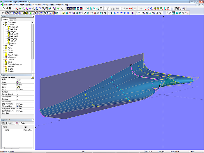
Model cv-aft-xloft.ms2: arrangement of master curves
Note, that the bottom edge of the surface curves upwards towards the transom. The master curves end at some height to form the fairbody in the region of the propeller.
The proper transition of the hull surface into the semi-circle of the propeller shaft is achieved by a Tangent Boundary Surface.
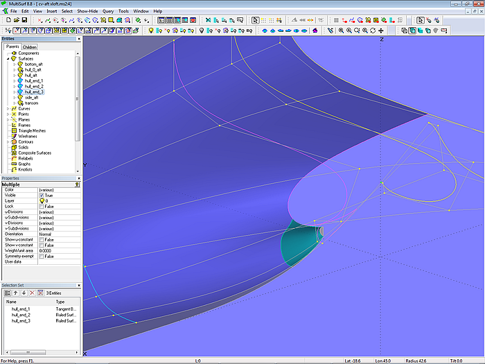
Model cv-aft-xloft.ms2: hull surface in front of the propeller defined by a Tangent Boundary Surface
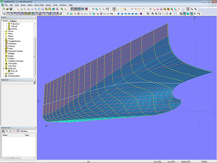
Model cv-aft-xloft.ms2: X-spline Lofted Surface
C-spline Lofted Surface
While no end conditions can be imposed on the lofting curves of the C-spline Lofted Surface the tangent entry of the aftship into the midbody must be created by clamping the surface edge – 2 identical mcs closely spaced. Model cv-aft-cloft.ms2 is an example for this method.
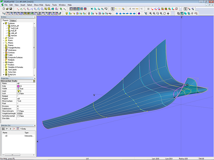
Model cv-aft-cloft.ms2: arrangement of master curves; mc7 and mc8 clamp the front surface edge.
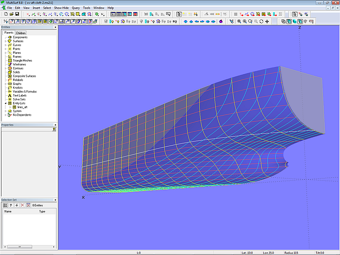
Model cv-aft-cloft.ms2: C-spline Lofted Surface
3 Various Subjects
Occasionally the aftship consists of two separate surfaces – main aftbody and skeg. Model container_vessel-aftship.ms2 gives an example. The main aftbody is an X-spline Lofted Surface on transverse B-spline mcs. The skeg is formed by a B-spline Lofted Surface on longitudinal B-spline master curves, while the end of the skeg is a Tangent Boundary Surface.
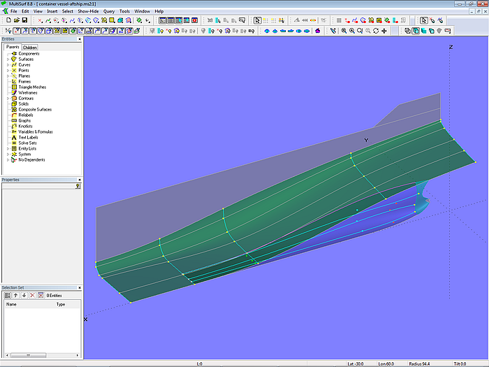
Model container_vessel-aftship.ms2 - main aftbody: X-spline Lofted Surface on transverse B-spline mcs; skeg: B-spline Lofted Surface on longitudinal B-spline master curves; skeg end: Tangent Boundary Surface
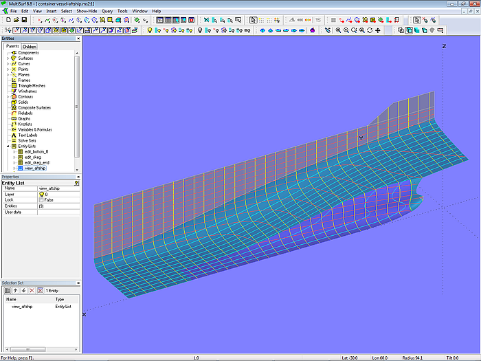
Model container_vessel-aftship.ms2: separately defined main aftbody and skeg
Model foreship-bulb.ms2 explains how to attach a separately defined bulbous bow to the main forebody of a ship hull. The bulbous bow is a B-spline Lofted Surface; its last and second but last mc are snakes on the forebody basis surface.
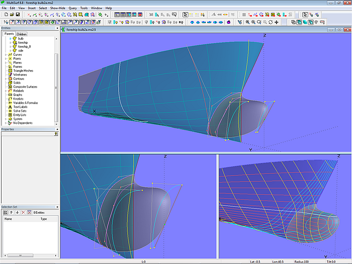
Model foreship-bulb.ms2: separate bulbous bow surface attached to basis forebody surface
====================================================================================