Decks and Superstructures
On decks, trunk cabins and bubbles
by Reinhard Siegel
Introduction
Small boats have no deck or cabin, but those are indispensable parts of larger vessels. This article explains various methods to model surfaces for decks and superstructures in MultiSurf.
Abbreviations used:
cp: control point (support point)
mc: master curve = support curve
cp1, cp2, ...: denotes 1st, 2nd, ... point in the list of supports of a curve. It is not an actual entity name.
mc1, mc2, ...: denotes 1st, 2nd, ... curve in the list of supports of a surface. It is not an actual entity name.
In the following the terms used for point, curve and surface types are those of MultiSurf. This may serve the understanding and traceability.
1 - Decks
Before we can model a cabin, we need a deck. Often a deck is little more than a foredeck and a deck at side. Nevertheless it is useful to start with a basis surface from bow to stern and then cut out the area covered by cabin and cockpit. In that way it is easy to change camber or sheer of the deck without paying attention to the fairness and joining of individual surfaces.
Method 1: Freeforming
Like a boat hull, a deck can also be modeled using the "master curve planking" method. This method provides the greatest flexibility with respect to the variation of amount of camber in longitudinal direction and shape of the deck beams in transverse direction.
It is a good idea to use the same surface type for the deck as is used for the hull and to locate the deck beam master curves at the same position as the master curves for the hull surface. Then both surfaces join watertight at the common edge.
C-spline Lofted Surface on B-spline mcs
Model deck_cloft_bcurve.ms2 shows a deck with B-spline Curves as deckbeam master curves. Each one is defined by 3 cps, where cp1 is the first point of the hull master curve. In order to make the deck-mc end perpendicular to the centerplane, cp2 is projected onto it as Projected Point cp3.
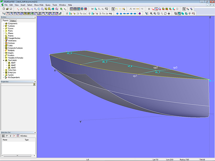
Model deck_cloft_bcurve.ms2 - deck surface by C-spline Lofted Surface on 4 B-spline Curve master curves
The vertex curve vl_d runs through all points cp2 of the mcs to serve as a guide for the harmonic distribution of the amount of beam camber over the length of the deck. If you look in 3D along this curve irregularities can easily be detected.
The further cp2 is positioned out towards the deck edge, the more parabolic the beam mc will be.
Of course, more than 3 cps can be used for the definition of the master curves, but the key to fairness is simplicity.
C-spline Lofted Surface on Arc-mcs
Alternatively, one can use a circular arc as mc. This is shown in model deck_cloft_arc.ms2.
Only the height of cp2 over cp1 at the sheer line plays a role here, not its y-position. Type 5 of the Arc entity ensures that the curve ends perpendicular to the centerplane.
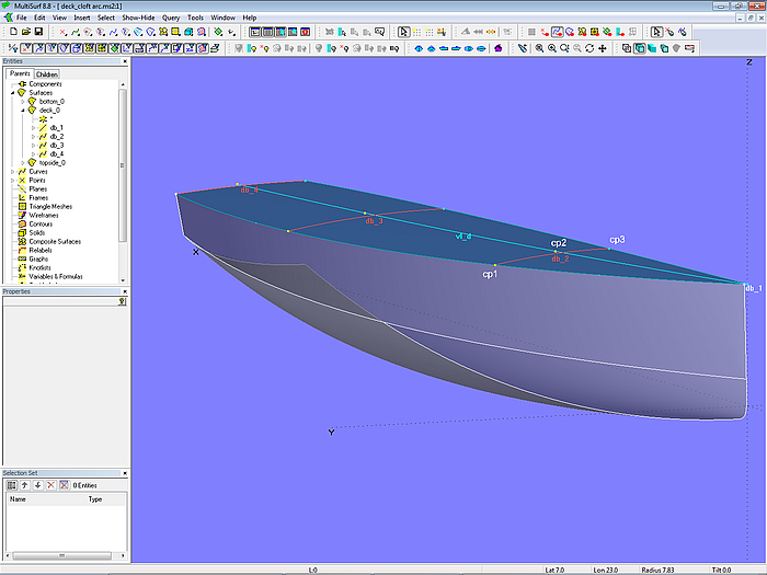
Model deck_cloft_arc.ms2 – deck surface by C-spline Lofted Surface on 4 Arc master curves
Arc Lofted Surface on longitudinal mcs
Up to now, the deck was supported by transverse mcs, similar to the hull surface. In model deck_arcloft.ms2 the longitudinal mcs vl_1, vl_d and c0 mount an Arc Lofted Surface. The curve vl_d, which is of the same type as the vertex curve vl_1 of the hull, determines the height of the deck camber; its cps lie exactly vertically above the 1st cp of the hull mcs. In order to end perpendicular to the centerplane the Arc Lofted surface is of type 5, while vl_d is projected onto it as c0.
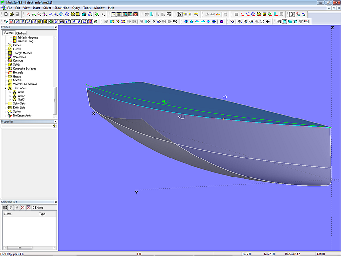
Model deck_arcloft.ms2 – Arc Lofted Surface supported by longitudinal mcs; c0 is the projection of vl_d onto the centerplane.
Alternatively, vl_d could also be a Relative Curve based on the vertex curve vl_1, its run controlled by a BGraph.
Method 2: Procedural Construction
Deckbeams of equal shape
Sometimes it is considered an advantage if all the beams of a deck have the same shape, that is, be sections of a single template. For example when laminated wooden deck beams are required.
Model deck_const_pattern.ms2 shows this approach. The beam template is the curve pattern, which is defined at the bow front as an Arc. The upper edge of the hull is the EdgeSnake n0. On this lies the Ring d_sheer. Now the curve pattern is cut in the Intersection Bead d_e0, where the intersection plane is parallel to the midship plane while passing through d_sheer. The portion from midship to d_e0 (SubCurve sub_pattern) is finally copied to the position of d_sheer (Copy Curve moving_cv). The Procedural Surface deck_0 repeats this construction for all positions of d_sheer.
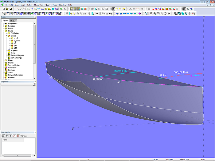
Model deck_const_pattern.ms2 – deck surface with equal beams by Procedural Surface
Since Ring d_sheer is located on the EdgeSnake n0, the deck has the same labeling as the hull surface; this ensures a watertight joint of both surfaces along the common edge.
Deck with constant camber ratio
Also by a procedural design a deck surface can be produced in which the amount of camber is a constant ratio of the deck width. Model deck_constant_camber_ratio.ms2 shows this variation.
The construction is again driven by Ring d_sheer, which lies on the top edge of the hull (EdgeSnake n0). This ring is projected onto the centerplane (Y = 0) in Projected Point d0. The Line half_chord between d_sheer and d0 is half the deck width at the position of d_sheer. Now the Bead ratio is set on this line whose t-parameter value is half the camber ratio. If the camber ratio is, for example, 15%, the t-value for ratio must be set to 0.075. (The position of a Bead on a line corresponds to the value of its parameter t, for t = 0.33 the Bead is at1/3 of the length, for t = 0.5 at the half, etc.)
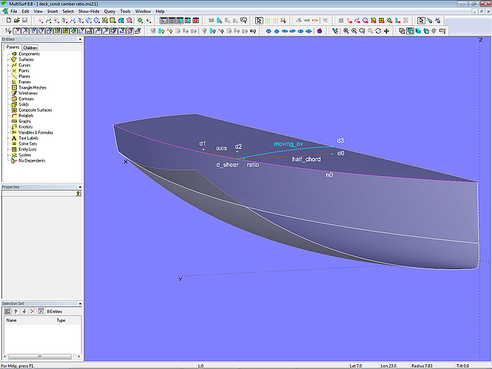
Model deck_constant_camber_ratio.ms2 – deck surface with constant camber ratio by Procedural Surface
The Bead ratio is now rotated 90 degrees upwards resulting in Rotated Point d2, which is then projected onto the centerplane as Projected Point d3. Finally, the Arc moving_cv is defined with the points d_sheer, d2 and d3. The Procedural Surface deck_0 now repeats this deckbeam construction for all positions of d_sheer on n0.
Method 3: Developable Surface Deck
A deck can also be created by a Developable Surface. This is shown in model deck_devsurf.ms2. The Developable Surface deck_0 is stretched between the top edge of the hull (EdgeSnake n0) and a deck beam at the rear (Arc db).
The price to pay for the easier production of a developable surface (only bending) is the limitation in form. The deck on the centerplane is straight, cross section cutting the deck run partially straight.
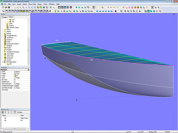
Model deck_devsurf.ms2 – deck by Developable Surface spanned between sheerline n0 and beam aft db
So much to deck constructions.
2 – The Trunk Cabin
Cabin 1 - Freeform
The simplest form of a superstructure is the box. It consists of side wall, front wall, rear wall and roof. The model trunk_cabin-1.ms2 shows an example.
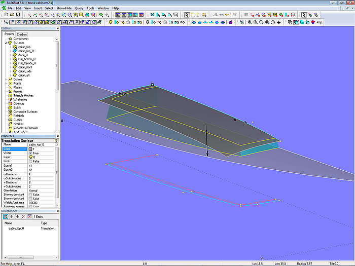
Model trunk_cabin-1.ms2 – box shaped superstructure
The base surface of the cabin top is a Translation Surface; its guiding curve is a B-spline curve on the centerplane, the moving or generating curve is a circular arc. The lower and upper edges of the cabin walls are defined in the XY-plane, then projected onto this base surface (as Projected Snakes). As a result, the superstructure remains the same in plan view when the deck is changed.
Note: it is important that the deck is a fair surface. Because a Projected Snake, which maps a smooth curve onto a non-fair surface, is not smooth. Consequently, a surface which dependents on this snake will be unfair.
All deck beams (cross sections) of the roof are the same. All sides are truly developable, but the roof is not. It would be developable too if the centerline of the cabin top is straight.
With this method only the roof surface is larger than the final parts, that is, all other elements do not need trimming.
With this design you can only change the curves for the upper and lower edges of the sides and then see if it pleases you. Special requirements, such as the slope of cabin side or front, are not possible.
Cabin 2 - Specifications
If there are geometrical specifications such as inclination of the cabin side is to be 10°, front is circular and sloped aft by 35°, a procedure as shown in model trunk_cabin-2.ms2 is convenient.
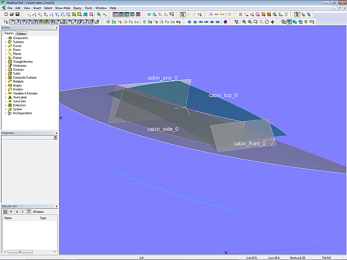
Model trunk_cabin-2.ms2 – basis surfaces of trunk cabin
The cabin surfaces are created initially as somewhat larger basis surfaces, each one shaped in accordance to the specifications.
Let us start with the roof. Required are beams, which can be laminated using a single template. A Translation Surface is chosen for this purpose. Guiding curve is the B-spline Curve c1 on centerplane, moving curve is Arc c2. Via the property "Dragging" their control points are constraint that c1 sticks on the centerplane and c2 is perpendicular to the centerplane.
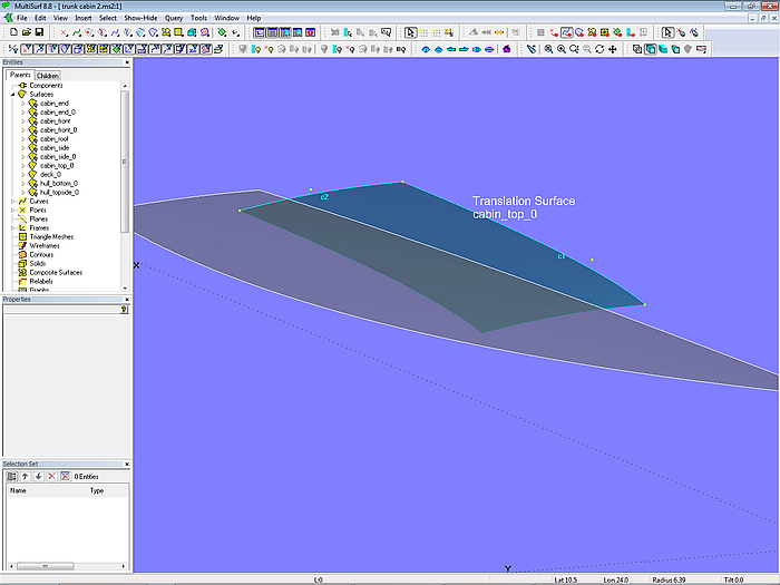
Model trunk_cabin-2.ms2 – construction of the basis surface for the cabin roof
The cabin front should be variable in position and inclination, and the curvature in the transverse direction an arc. Therefore an XYZRing (ring1) is set on Snake n0 and together with the points pt1 and pt3 a 3-point Frame is defined. Based on this frame are the points pt2, pt4 and pt5, which determine the circular arc c3 (here it is an Arc, but it could also be a RadiusArc entity, which allows to specify a wanted radius value). The Line line1 is spanned between pt1 and pt2, and together with c3 the Translation Surface cabin_front_0 is created.
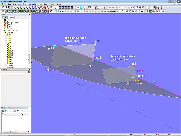
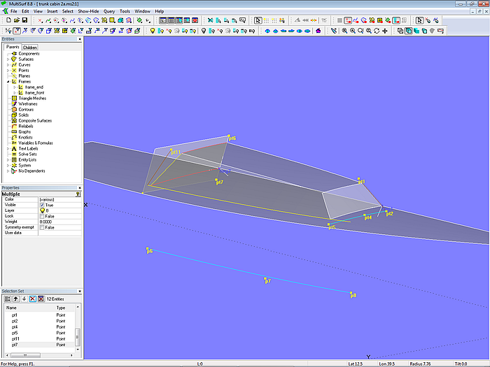
Model trunk_cabin-2.ms2 – construction of the basis surfaces for cabin front and cabin end
The cabin end should be flat and only variable in inclination and position. With Ring ring2, points pt6 and pt8 the aft frame is created and points pt7 and pt9 based on it. Pt10 is a CopyPoint that ensures flatness of the rectangular B-spline Surface cabin_end_0.
Note: a flat rectangular surface can be generated with the fewest objects simply by 4 points and a B-spline Surface of type 1 in both the u- and the v-direction. Three of the points determine the location of the surface in 3D space, while the 4th point is a Copy Point with the other points as parents.
The cabin side should have a constant inward slope. It is made by a Translation Surface also. On the XY-plane the form of its lower edge is defined by the B-spline Curve c0. This one is then projected onto the deck as Projected Snake n1. At the aft end of n1 resides the Ring ring3, being support for Point pt11, which controls height and inclination. With Line line2 between ring3 and pt11 as generator and snake n1 as path the Translation Surface cabin_side_0 is determined.
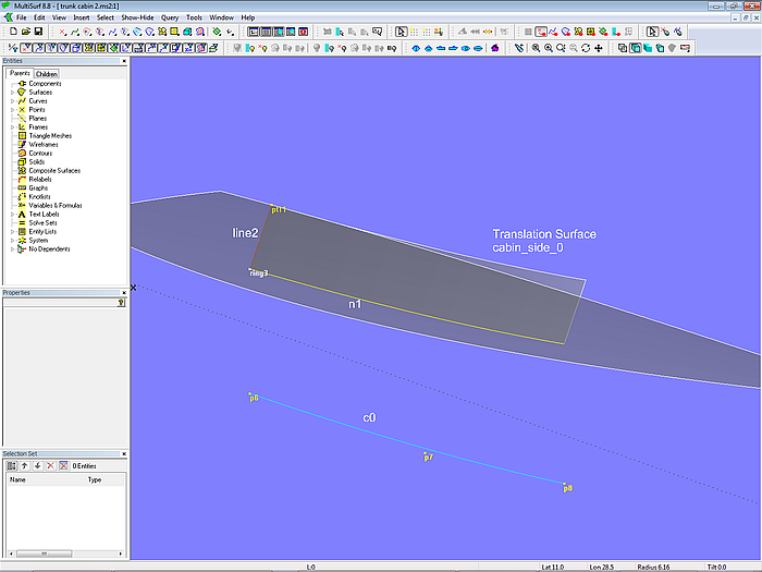
Model trunk_cabin-2.ms2 – construction of the basis surface for the cabin side
Now, that the basis surfaces are created, the next step is to trim them against each other. Let us look first at the cabin front.
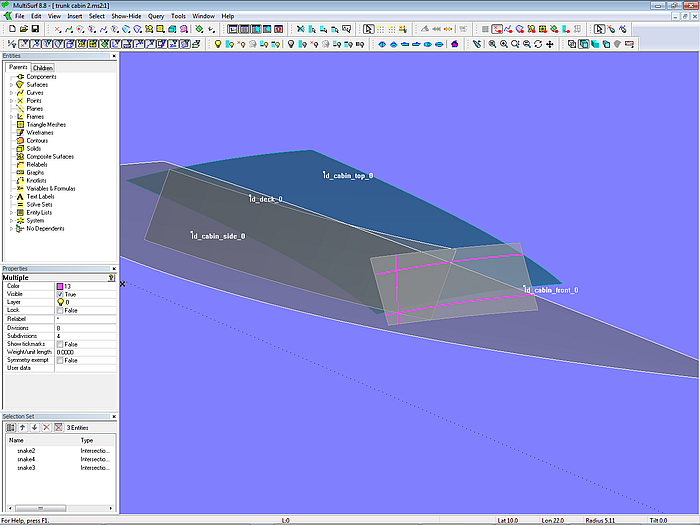
Model trunk_cabin-2.ms2 – intersections of front by deck, roof and side
The front is cut by the roof, deck and side, resulting in 3 Intersection Snakes, all residing on the Translation Surface cabin_front_0. The extending portions of these snakes are cut off by SubSnakes serving as the boundaries of the final Trimmed Surface cabin_front.
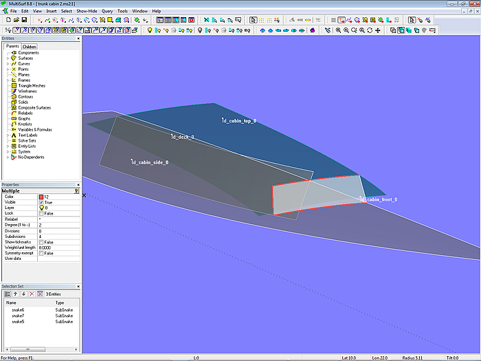
Model trunk_cabin-2.ms2 – final front of cabin by Trimmed Surface
Cabin side and end surfaces are treated in the same way. First, the intersection with the neighboring surfaces are determined (Intersection Snakes), next, extending portions trimmed via SubSnakes, and finally Trimmed Surfaces created.
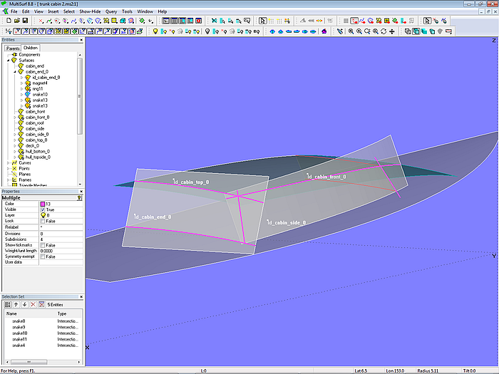
Model trunk_cabin-2.ms2 – intersections of deck, side, roof and cabin end
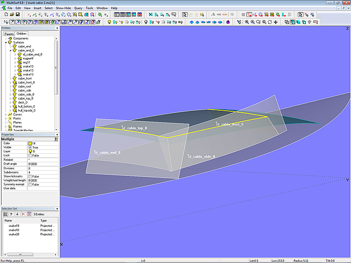
Model trunk_cabin-2.ms2 – use of existing SubSnakes for Trimmed Surface cabin_top
With regard to the cabin top surface there is no need to intersect it with the surrounding basis surfaces. Simply project the already existing SubSnakes onto the roof (Projected Snakes). This saves repeated work.
Model trunk_cabin-2.ms2 – final surfaces and their defining points and curves
It is very convenient to maintain an Entity List which holds the objects that define the shape of the superstructure. Then you can quickly get all the points and curves on the screen, which really control form and position of the individual surfaces. Auxiliary objects such as rings for trimming intersection snakes, these themselves or their SubSnakes do not need to be displayed, these are just things which can stay in the background. Of main interest are the finished parts and the points (handles) and curves which control their shape.
To show the content of an Entity List:
- in the Entities manager right-mouse-click on the name of the Entity List, then select “Show Parents” from the context menu, or
- in the Entities manager click on the name of the Entity List, then click the button “Show Parents” from the “Show-Hide” toolbar
In this model here in question, the lower edge of the cabin side is a Projected Snake on the deck. This has the advantage that one immediately knows where the side of the cabin meets the deck, so one can see immediately how wide the gangboard is.
The two Rings ring1 and ring2 determine directly where the cabin front and the cabin end are located on the deck centerline.
If, however, the deck is changed, for example, it is given some more camber, then the position of the snake will change in height, and thus the bottom edge of the cabin side also moves slightly upwards. While the rings on centerline remain in place with respect to the longitudinal position, they go up a bit, dragging their frames along, and everything that depends on them.
In model trunk_cabin-3.ms2, on the other hand, all basis surfaces are independent of the deck. The basis surfaces are basically defined in the same way as before, but the bottom edge of the cabin is below the deck surface. The position of the front and end surfaces is defined only indirectly by the points pt2 and pt7.
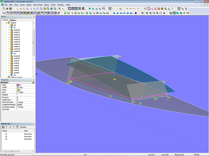
Model trunk_cabin-3.ms2 – basis surfaces for a cabin without being dependent in shape on deck surface
As can be seen by the Intersection Snakes, if the camber or sheer of the deck is modified, the construction now dips more or less deep into the deck. But otherwise the superstructure geometry remains unchanged. What will change, however, is the width of the deck at side and the cabin height above deck.
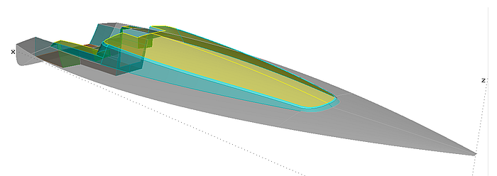
3 – The Freeform-Superstructure (Bubble Cabin)
B-spline Lofted Surface on Transverse Mcs
In the box-shaped design, there were separate surfaces for front, side and top. In model bubble_cabin_bloft-1.ms2 these 3 elements are formed by a single surface of the type B-spline Lofted Surface. This kind of surface allows round, soft transitions between front, side and roof.
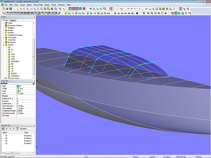
Model bubble_cabin_bloft-1.ms2 – arrangement of transverse B-spline master curves
The support curves of the B-spline Lofted Surface are 4 B-spline mcs, which run in transverse direction. The mc arrangement is similar to that for a hull rotated by 90 degrees.
B-spline Lofted Surface on Longitudinal Mcs
In model bubble_cabin_bloft-2.ms2 the support curves run in longitudinal direction. This makes it possible to place a mc as a snake on the deck, defining directly the shape of the cabin edge at deck level. So there is not need to trim the cabin at the deck.
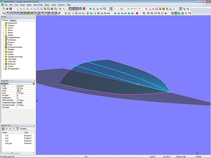
Model bubble_cabin_bloft-2.ms2 – arrangement of longitudinal master curves
Tangent Boundary Surface
The ultimate bubble superstructure can be created using the Tangent Boundary Surface. On the one hand, the shape is defined by its 4 edge curves. On the other hand, the surface can be arbitrarily deformed by internal control points.
In the model bubble_cabin_tbs.ms2 the shape of the lower edge is first created as curve c1 and then projected onto the deck as Projected Snake n0. The Ring r0 divides the Projected Snake n0 into the SubSnakes n1 and n2. The aft edge is defined by the B-spline Curve c2, and the profile on centerplane is given by the B-spline curve c3. Thus, all the 4 boundary curves of the Tangent Boundary Surface are determined.
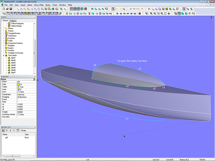
Model bubble cabin tbs.ms2 – bubble shape superstructure by Tangent Boundary Surface; arrangement of boundary curves
If the shape of the cabin is not yet as desired, the surface can be modified further via internal control points (with a selectable number both in u- and v-direction of the surface).
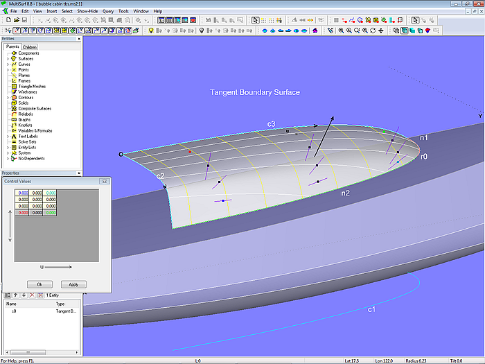
Model bubble cabin tbs.ms2 – the interior portion of the Tangent Boundary Surface can be formed by internal control points.
4 – Somewhat more complex superstructures
Rounded front
A box-shaped design as in the trunk_cabin models can have rounded corners. Model trunk_cabin_cornerpost.ms2 shows how to do something like that. The basic construction is the same, separate basis surfaces for side, front, etc. Between front and side the surface cabin_front_round of the type Rolling Ball Fillet is added. As the name implies, this surface can be thought of as a sphere that rolls between the two surfaces, sweeping a rounding which extends between the path of all the contact points on the one surface and the path of all contact points on the other surface.
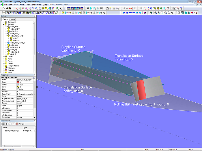
Model trunk_cabin_cornerpost.ms2 – basis surface for the rounding between cabin front and side
As with the other surfaces, the rounding is intersected with the adjacent surfaces (Intersection Snakes) and then the desired portion of the surface is generated as a SubSurface or Trimmed Surface.
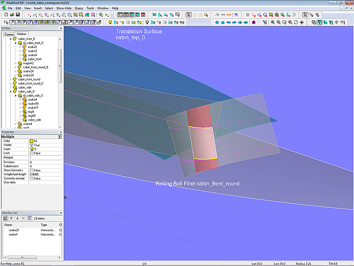
Model trunk_cabin_cornerpost.ms2 – final rounding between intersection with deck and cabin top (SubSurface)
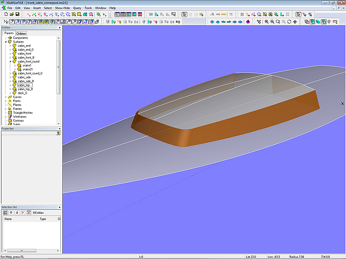
Model trunk_cabin_cornerpost.ms2 – finished cabin surfaces
Rounded edges
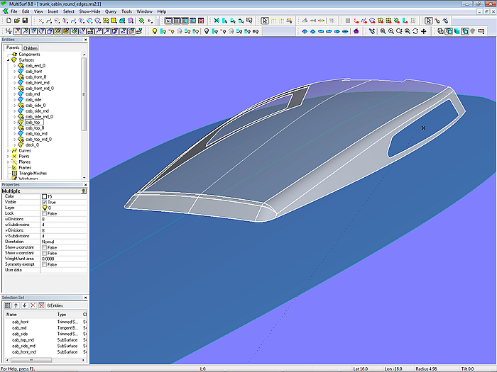
With the Rolling Ball Fillet, the edges along the cabin faces can also be rounded off. Model trunk_cabin_round_edges.ms2 shows an example.
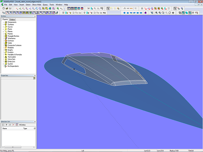
Model trunk_cabin_round_edges.ms2 – rounding of cabin edges using Rolling Ball Fillets
Three roundings are added to the cabin basis surfaces: the Rolling Ball Fillet cab_top_rnd_0 between cab_top_0 and cab_front_0, the Rolling Ball Fillet cab_front_rnd_0 between cab_side_0 and front, and the Rolling Ball Fillet cab_side_rnd_0 between roof and side. All fillets have the same radius.
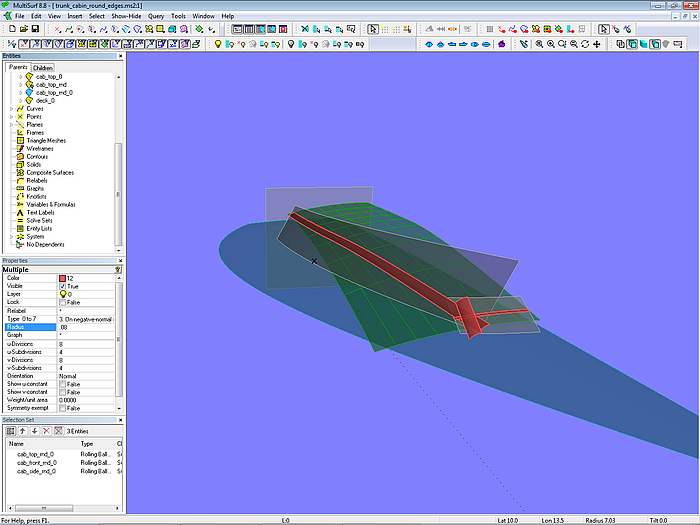
Model trunk_cabin_round_edges.ms2 – the basis rounding surfaces meet at the front.
The fillets meet in the corner between roof, side and front.
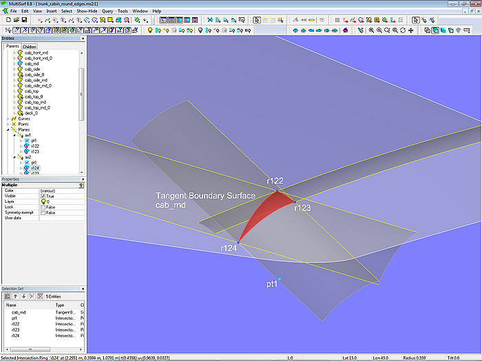
Model trunk_cabin_round_edges.ms2 – spherical triangle between the rounding surfaces in the corner of side, roof and front
The sphere, which rolls along the intersection of side and roof of the cabin knocks against the front wall (r123), thus its rounding surface ends before the front. When the sphere travels along the intersection of roof and front, it hits against the side (r124), thus its rounding surface stops before the side. When the sphere moves along the intersection of side and front, it hits the roof (r122), its rounding ends in front of the roof. Therefore a gap arises between the 3 rounding surfaces. This gap is closed by a part of the surface of the sphere (center point pt1) fixed in the corner; the rounding here is a spherical triangle.
In the model trunk_cabin_round_edges.ms2 this triangle is produced by the Tangent Boundary Surface cab_rnd.
Model trunk_cabin_round_edges.ms2
Front with flat windows
The model front_windows-1.ms2 shows the easiest way to create surfaces for front windows. The restrictions are flatness and rectangular shape.
Starting point is the XYZRing r0 on the deck centerline. From it depends the point pt2 on centerplane; it controls the inclination of the inner window. Together with point pt1 they determine the 3-point Frame F0, to which all further points then refer.
The half width of the window determines the point pt3. For the window to be rectangular, the CopyPoint pt4 is created. With r0, pt2, pt3 and pt4 the B-spline Surface window1_0 is determined. (A flat rectangular surface can be created with a minimum of 4 points and a B-spline Surface, one point being a Copy Point of the other 3 points.)
The adjacent window window2_0 is also a B-spline Surface with 4 Cps; pt5 is defined in polar coordinates, so the radius is the width of the window, and the latitude is the angle to the inner window.
The outer window window3_0 is defined in an analogous manner. If the bending angle is to be as large as for the neighboring surface window2_0, the value for latitude for the point pt7 must be the double of the value for pt5.
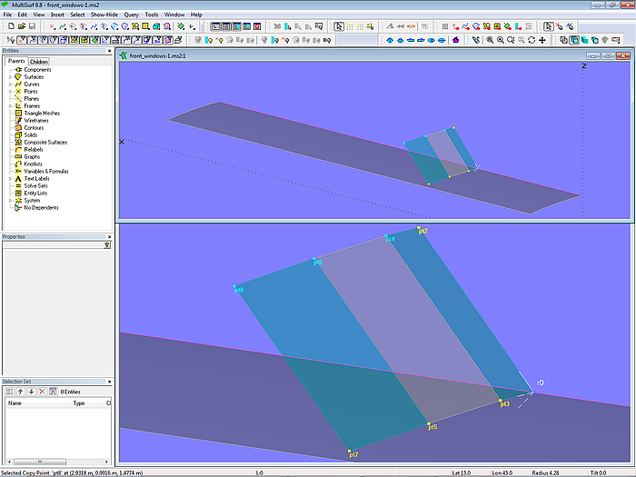
Model front_windows-1.ms2 – arrangement of control points for 3 planar rectangular surfaces (front windows)
If the window surfaces are not to be rectangular, but have a different width at the upper edge than at the lower edge, the method shown in the model front_windows-2.ms2 can be used.
A Line (line1) is spanned between the points pt4 and pt6, and the Arc-length Bead e0 is set on it. For the B-spline Surface window2_0, the bead is then used instead point pt6. The window surface is still planar (ensured by Copy Point pt6), but you can now control the desired upper width by e0.
The outer window surface can be defined in the same way.
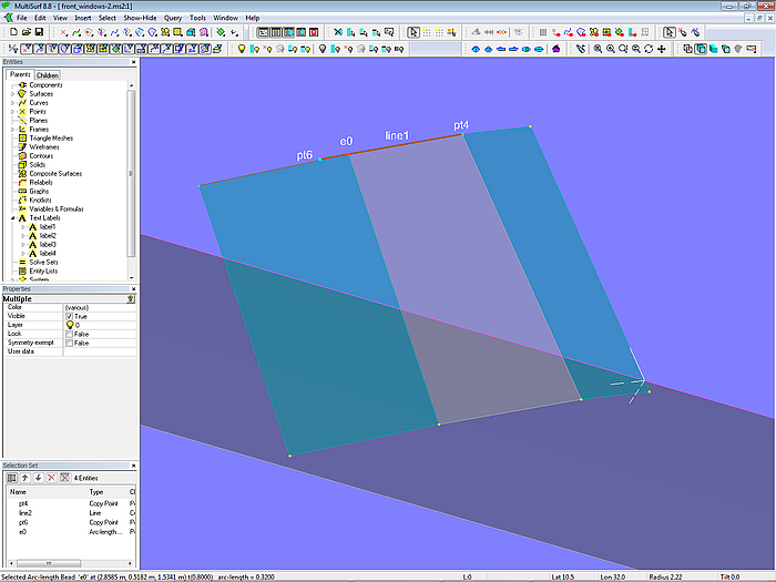
Model front_windows-2.ms2 – arrangement of control points for variable width of upper edge
Model front_windows-3.ms2 shows an application of the method explained in the foregoing.
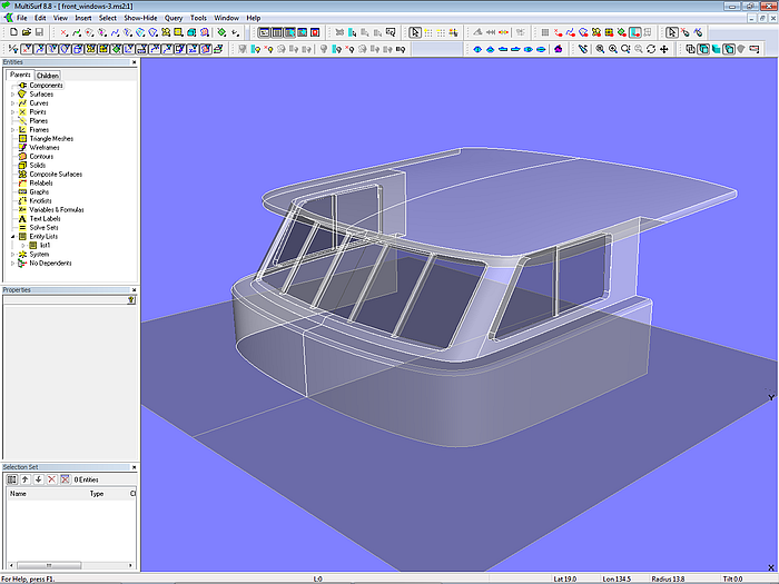
Model front_windows-3.ms2
5 – Complex Superstructures
Complex superstructures are a combination of simple elements, the modeling of which has been shown in the preceding sections. Here are some examples.
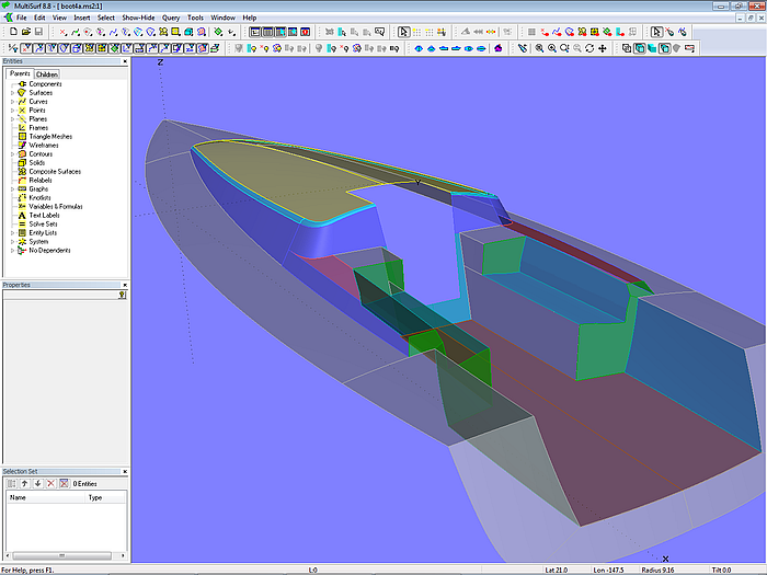
Model design-4.ms2 - 10 m sailboat – superstructure and cockpit
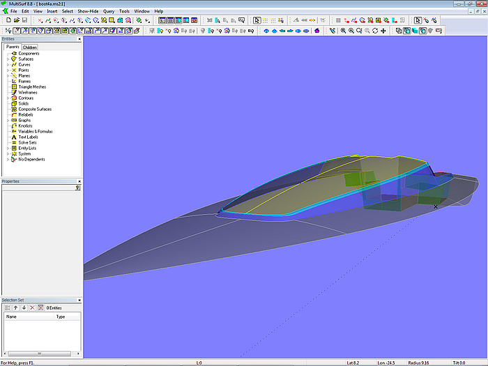
Model design-4.ms2 - 10 m sailboat - superstructure
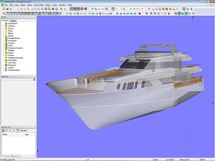
120 ft motor yacht (Russel Dowland design)
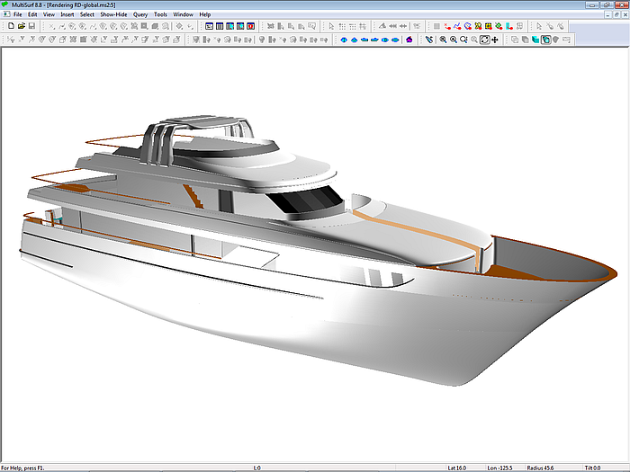
120 ft motor yacht (Russel Dowland design)
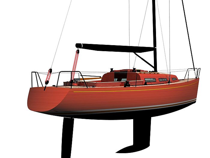
10 m sailing yacht (Juliane Hempel design)
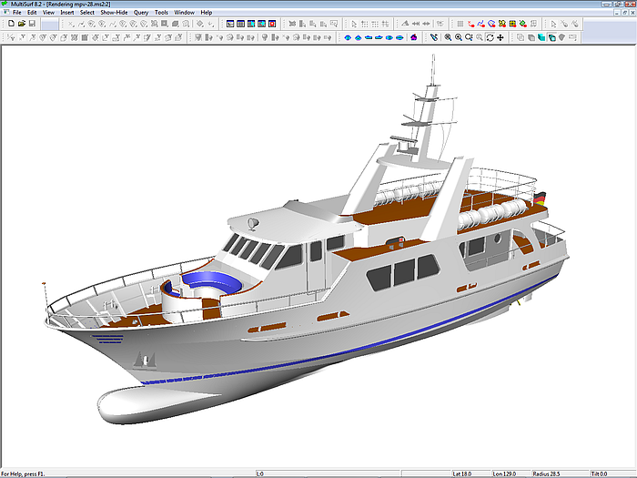
27 m passenger vessel (CL Shipdesign)
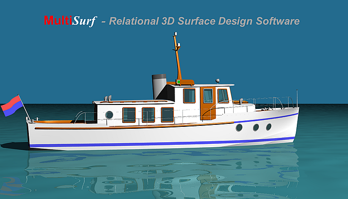
11.5 m classic motorboat (CL Shipdesign)