Developable Surfaces in MultiSurf
Hull, Deck, Superstructure
by Reinhard Siegel
Contents
Introduction
1 What is a developable surface?
- 1.1 Basic shapes - cylinder, cone, tangent surface
- 1.2 The general developable surface - combination of cylinder, cone and tangent surface
- 1.3 Ruled surface
2 The advantages of developable surfaces
3 Developable surfaces with MultiSurf
- 3.1 Developable Surface
- Determination of generators (rulings)
- Breaklines
- The arrangement of rulings and its effect on fairness
- 3.2 Fairing of developable surfaces
- General information
- Radiating rulings
- Curved trailing edge
- Partly straight run of a support curve
- Support curve with inflection point
4 Hull design with developable surfaces
- 4.1 Modern multichine hull
- 4.2 Classic multichine hull
- 4.3 Powerboat
5 Special hull shapes
- 5.1 "Radius chine" hull
- 5.2 Hull with non-developable surface patch
- 5.3 Hull with conical surface
6 Deck with developable surface
7 Superstructure with developable surfaces
8 Surface expansion
- Expanded Surface
- Transom Development
Introduction
Whenever the manufacturing capabilities of the builder and/or economic reasons are taken into account in the construction of a boat the chine hull is selected. Chine form hulls are not commonly looked upon with pleasure and in contrast to round bilged hulls their resistance is increased. However, since the beauty of a boat is mainly defined by her proportions, it should be possible to design chined hulls without neglecting aesthetics. And as far as performance is concerned, especially when using multiple chines, hull forms can be created that are hardly inferior to the round bilge competition. In fact, at high speeds (powerboats) the chined hull is superior to the round bottom version in terms of resistance and sea behavior.
Not every chine hull automatically features developable surfaces. It is a common misconception to believe, that a hull with sections that run straight between sheer, chines and keel is made up of developable surfaces. On the contrary, deck side, chines and profile as curves in space must be shaped to meet very specific conditions, in order to span them with developable fair surfaces.
What might ultimately decide whether to build a hull of the chine form type, there is no reason not to use the advantages of a surface kind, which is employed successfully throughout the technology.
Developable surfaces can be used easily for hull skin, deck and superstructures. They enable even the amateur to save material, cost and time to create a good product.
Abbreviations used:
cp: control point (support point)
mc: master curve = support curve
cp1, cp2, ...: denotes 1st, 2nd, ... point in the list of supports of a curve. It is not an actual entity name.
mc1, mc2, ...: denotes 1st, 2nd, ... curve in the list of supports of a surface. It is not an actual entity name.
In the following the terms used for point, curve and surface types are those of MultiSurf. This may serve the understanding and traceability.
1 What is a developable surface?
The definition of the developable surface is in words:
"A curved surface is called developable if it can be rolled out flat onto a plane only by bending, that is without any change of length of the surface fibers."
Such an expansion is by no means possible for every surface. A portion of the surface of a sphere can only be flattened by force, with extension and cracks occuring at the edges, and wrinkles and compression in the middle. However, a developable surface can be flattened by bending only.
1.1 Basic shapes - cylinder, cone, tangent surface
A simple example of a body with a developable surface is a can, geometrically seen a straight circular cylinder (a). If it is cut along the bottom and lid and along the shell, it is easily flattened. It can also be put on a flat surface and completely rolled off. The trace on the support is the development of the can, a rectangle with the height of the can and a side length according to its circumference. Another example is the straight circular cone (b). Rolled onto a flat surface, the expansion of its shell is a segment of a circle.
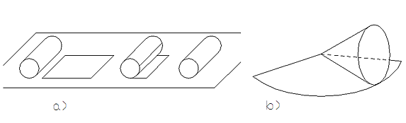
Developable surfaces: straight cylinder and straight circular cone
Slightly more complicated examples of developable surfaces are the general cylindrical and conical surfaces. A cylindrical surface (a) is created when passing through all points of a curve in space (guide) a continuous series of straight lines (generators, rulings) that run parallel to each other. If the generators all intersect at one point, they describe a conical surface (b). That any cylindrical or conical surface can be expanded by bending only can be understood easily, when one imagines to replace it by a polygonal prism or a polygonal pyramid, with all the individual flat surfaces hinged together along the edges. These structures can be unfold onto a plane effortless.
Basic shapes of developable surfaces: cylindrical surface, conical surface, tangent surface
Except cylinder and conical surface only the tangent surface (c) can be flattened just by bending. The tangent surface is created by the continuous sequence of tangents to a curve in space.
1.2 The general developable surface - combination of cylinder, cone and tangent surface
The general developable surface consists of pieces of cylinders, cones and tangent surfaces attached along common generators (rulings).
General developable surface - combination of cylinder, cone and tangent surface
1.3 Ruled surface
Developable surfaces are often confused with ruled surfaces The continuous movement of a line in space covers a ruled surface. The individual positions of the line are the generators of the surface.
The distinction between developable surfaces and ruled surfaces is important because all developable surfaces are ruled surfaces. But not all ruled surfaces are developable.
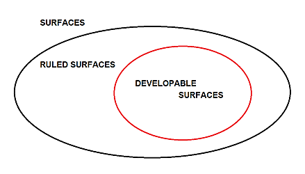
Developable surfaces are a subset of the ruled surfaces.
An example of a ruled surface, that can not be expanded by bending alone, is the helical surface, which is swept out by the straight axis of the two blades of a propeller as it turns and moves forward. It is a ruled surface, the successive positions of the blade axis are the generators. But it can not be flattened. A metal strip can not be shaped like this without stretching.
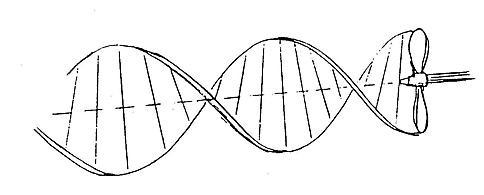
Helical surface - example of a ruled surface that can not by expanded by bending alone
Ruled surfaces and developable surfaces is in common that they are created by straight generators. The crucial additional requirement, that a ruled surface is also a developable surface, is this:
All along a generator, the surface normal must have the same direction.
Or more clearly expressed:
A developable surface is touched by a plane always along a generator.
A plane always touches a developable surface all along a generator (ruling).
The can rests completely along a shell line on a table, as well as the cone. With the helical surface, the surface normal runs more and more perpendicular to the propeller shaft, the more it is approached to. A sphere touches a plane in a single point. Which makes it clear why a boat with developable outer skin can not be round bilged. If you were to place a round bilged hull on a flat surface, it would touch at one or more single points, but never along a straight line.
Ruled surface in MultiSurf
The Ruled Surface entity in MultiSurf is created from two curves (support curves) by connecting points on each parent curve having equal t-parameter values with Lines (rulings). A Ruled Surface interpolates both support curves, leading and trailing edges are straight.
Ruled Surface
In special cases, a Ruled Surface is developable. For example, is curve 2 a translational copy of curve 1, then the Ruled Surface is a general cylinder. Is curve 1 or curve 2 a point, then the Ruled Surface is a general cone with this point as apex. Cylinders and cones are always developable.
Translational surface with straight generator
The Translation Surface entity in MultiSurf is formed by sliding a generating curve along a guiding curve without twisting, that is, all generators are parallel to each other. If the generating curve is straight, the Translation Surface is a cylindrical surface. Because cylindrical surfaces are always developable, a Translation Surface with a Line entity as generator is a developable surface.
Developable surfaces for deck, cabin side, cabin front etc. can easily be constructed with Translation Surfaces.
2 The advantages of developable surfaces
Developable surfaces can be rolled out flat onto a plane only by bending. Or "rolled up" from flat material into a spatial shape. A change in length of the surface fibers, i.e. contraction or expansion, does not occur. If the shell of hull, deck and superstructure of a boat are made from developable surfaces, the following advantages arise:
- Use of plate material. Hull, deck, superstructures can be completely made by flat plates (steel, aluminum, plywood, GRP sandwich). Plate material is available in bigger size, what results in fewer seams.
- No special manufacturing capabilities required. Plates are easier bended than stretched or compressed, so even large metal hulls can be built by hand tools, while otherwise the forming process from flat stock to compound-curved shell plating requires machine tools (roller planishing, die pressing etc.. Therefore very suitable for amateur boat building.
- No fitting work. The expanded outline of the hull plating can be determined accurately. Exact fitting bulkheads, frames, stringers, etc. can be prefabricated.
- The effort for the foundation structure is reduced to a minimum. A few negative frame molds are sufficient to hold the individual plates in the correct position to each other. By stitching the plate edges the hull shape results automatically.
- Short construction time. Compared to an equal sized round bilge hull an average time saving for the shell construction of 50% arises.
- Smooth shell plating. Hull plates can be joined together first, then internal structure like frames, bulkheads, etc. added. Especially with metal hulls this reduces the tendency for bumps to occur.
All advantages summarized: the construction of boats with developable surfaces is simple and at good value.
3 Developable surfaces with MultiSurf
3.1 Developable Surface
The surface entity Developable Surface in MultiSurf has two curves in space as parents (support curves). It is created as follows.
Determination of generators (rulings)
First, a point A is selected on curve 1. Then a point B on curve 2 is searched for such, that a plane simultaneously touches both curves in these points. The connecting line AB is then a generator or ruling of the Developable Surface. Next another point A is selected on curve 1 and again the corresponding point B on curve 2 is determined. One can visualize this procedure in such a way that a plane is put against both curves and rolled on. The generators are at the same time the bending lines, along which the surface is bent when expanded, or on the contrary, "rolled up", when build from a flat surface.
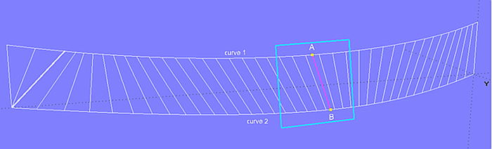
Contact plane - generation of the rulings of the Developable Surface
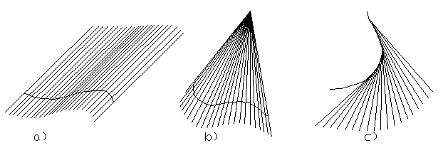
The procedure described above is continued until rulings were found between start and end of both support curves. If the end is reached on one of the curves, but not yet on the other one, the remaining rulings run radiating. In the example above this is the case at the left end of curve 2.
If rulings (generators) run parallel to each other, the corresponding surface portion is cylindrical; if fanned out, it is part of a tangent surface; and if rulings share the same end point, it is part of a conical surface.
Breaklines
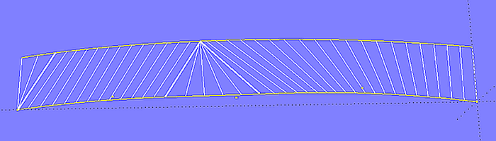
If a ruling in a Developable Surface is displayed on the screen in bold fashion, this marks a so-called breakline. A breakline is a curve with u = constant or v = constant in an area indicating where a discontinuity of slope, parameter speed or curvature occurs. For a Developable Surface a breakline features a spot where rulings have the same endpoint, so radiate.
Breaklines in a Developable Surface are an indication to take a closer look. It can but it does not have to be a problem.
On the one hand, intersections made in the area of radiating rulings may be unfair. In the following more to this topic.
On the other hand, breaklines can cause an error message for children surfaces, which depend on the calculation of geometrical properties of the Developable Surface, for example Rolling Ball Fillet, Sweep Surface or Tangent Boundary Surface. Geometrical quantities like the direction of the tangent at the surface edge, where rulings have the same endpoint, can not be calculated (zero distance between points).
The arrangement of rulings and its effect on fairness
A Developable Surface is not automatically a smooth surface. Take a sheet of paper and fold it together arbitrarily. It is and remains a developable surface.
Even if both support curves run in a harmonious fashion, irregularities in surface fairness can occur. The arrangement of the rulings gives clear indications in this respect.
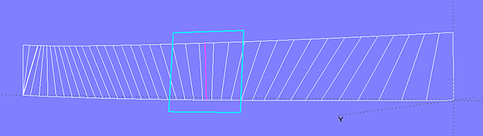
Model 2triangles_a.ms2 holds a Developable Surface spanned between two skewed Lines (curve 1, curve 2). There is a clear break in the longitudinal section. The run of the rulings and the breakline shows that the surface consists of two triangular flat portions.
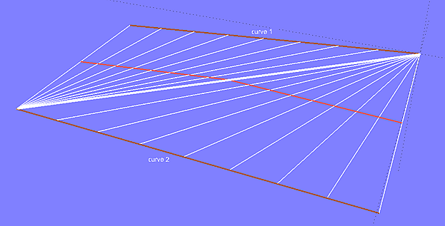
Model 2triangles_a.ms2 – Developable Surface spanned between two skewed Lines
While point A progresses along curve 1, point B stagnates on curve 2. When point A has reached the curve end, point B moves along curve 2, while point A now in turn stagnates.
Whenever ruling endpoints do not progress, but stagnate, or change the moving direction, adverse effects on the shape of the surface can arise. If the rulings run regularly, so do waterlines, sections, etc.
The ruling arrangement depends only on the shape of the two supporting curves relative to each other. If the surface is not smooth, the shape of one or both curves must be modified.
For the Developable Surface the type of its parent curves is not important. For example, for the bottom surface of a hull one can use a C-spline Curve for the chine, and a B-spline Curve for the keel profile inclusive the stem forefoot.
In contrast to surface types such as the Lofted Surfaces, the parameter distribution and the number of control points (cps) of the support curves have no influence on the ruling arrangement. Because of the way, a Developable Surface is created (roll off of a plane), the shape of the supports is crucial.
The curvature of the surface is crosswise to the rulings (bending lines, rolling lines). When rulings run in transverse direction of a hull, sections are straight. When running inclined, sections are convex. The more oblique the rulings, the more convex the sections. The shape of sections, buttocks, waterlines of a Developable Surface can only be modified by the arrangement of the rulings, hence via its support curves and their run relative to each other.
Severely curved foreship section due to sloping rulings
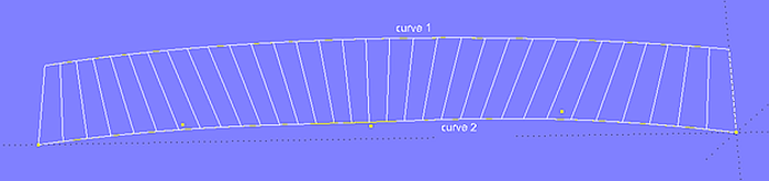
If in model 2triangles_a.ms2 the Developable Surface is replaced by a Ruled Surface, the picture will change completely. See model 2triangles_b.ms2. There is no breakline.
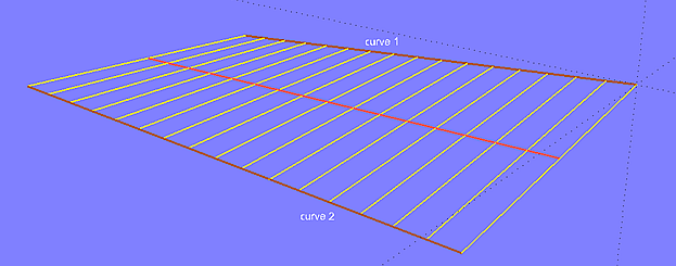
Model 2triangles-b.ms2 - Ruled Surface between two skewed Lines
Both surface types is in common the straight generators, but the method, how these are determined, is quite different. That is why it is not a good idea, to replace a Developable Surface by a Ruled Surface in order to achieve a regular arrangement of rulings. The developability will be lost.
It should always be kept in mind that developability means a restriction in design. The Developable Surface, set up between its two support curves, has its own laws to which the designer must adapt with his form wishes.
3.2 Fairing of Developable Surfaces
It has already been mentioned, that a Developable Surface is not automatically a smooth surface. As well, that the arrangement of the rulings depends only on how its two support curves runs relatively to each other.
General information
- One must try to harmonize the run of the rulings. For example, if in the middle of a Developable Surface the rulings are more or less perpendicular, then tilt aft and finally become vertical again towards the end, this will mean for the shape of the sections: no curvature in the middle, then increasing, then decreasing curvature. In a round bilged hull such a sequence of sections would not be accepted. By changing the support curves one should try to get sloping rulings until the aft edge of the surface.
- One must try out on which of the two curves the rulings are most likely to react in the desired way.
- Whenever a sequence of sections starts twisting increasingly, they will show severe curvature, caused by the obliquely running rulings. The only remedy is to reduce the twist of the sections.
- A stem with a strongly curved forefoot poses more problems on harmonious sections than a gradual transition between fairbody profile and stem.
- Hull plates, narrow in transverse direction but with strong curvature must be pre-bent by machine if built from metal. Sheets of plywood or GRP sandwich must be partially cut aligned to the rulings so that they are less rigid.
In the following methods are shown how the shape of Developable Surfaces can be influenced within limits. As an example, the bottom surface of a powerboat is chosen, spanned between the chine curve (chine) and the bottom contour (keel). Because these curves can show little curvature in the aftship, the arrangement of the rulings (generators, rolling lines, bending lines) can be irregular here.
Radiating rulings
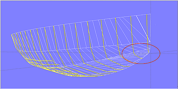
When both supporting curves end at the same X-position, rulings tend to be radial at the end of one curve. In the model bottom_panel-1.ms2 it can be seen that those rulings cause an inharmonic curvature of the aft sections.
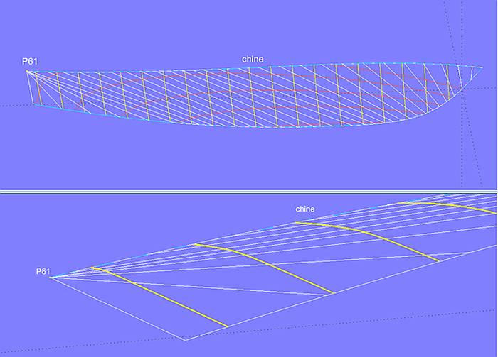
Model bottom_panel-1.ms2 - bottom panel of a powerboat hull. The rulings aft radiate to the end of curve chine.
If point P61 is raised, the rulings run parallel to the trailing edge and the sections become more evenly.
Model bottom_panel-2.ms2 - raising point P61 increases the curvature of chine, what has a favorable effect on the run of the rulings and thus on the shape of the sections.
Curved trailing edge
If in the aftship a convex section shape is strived for, the rulings must be prevented to radiate. There are several methods to achieve this.
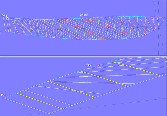
Method 1 - longer support curve
One possibility is shown in model bottom_panel-3.ms2. The curve chine does not end at the stern, but extends somewhat beyond.
Model bottom_panel-3.ms2 - the curve chine ends aft of the transom. As a result, the rulings fan out.
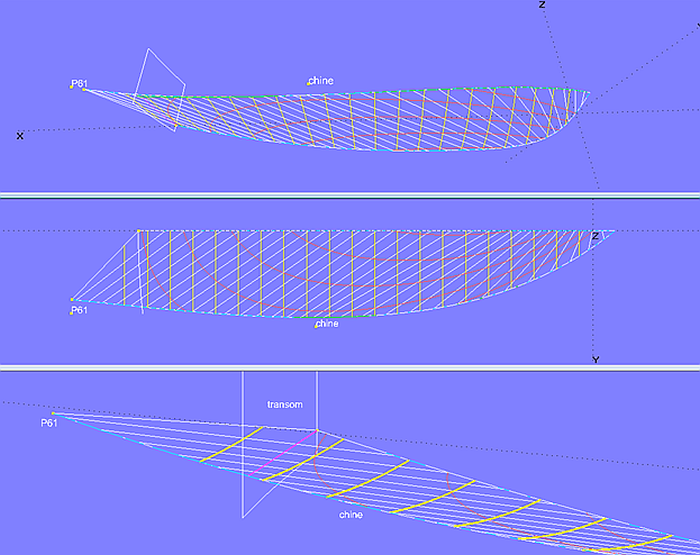
Method 2 - SubCurve
Another possibility is demonstrated in model bottom_panel-4.ms2. Both parent curves end at the stern, but curve chine is extended by a SubCurve entity. First, two beads are created, one bead at the start and one bead (e1) at the end of chine, then a SubCurve (extended_chine). Because in MultiSurf curves are also defined beyond the nominal t-parameter range 0 – 1, an extension of the curve is obtained, if e1 is shifted beyond the curve end (t > 1). This method is often sufficient to give the rulings the desired change.
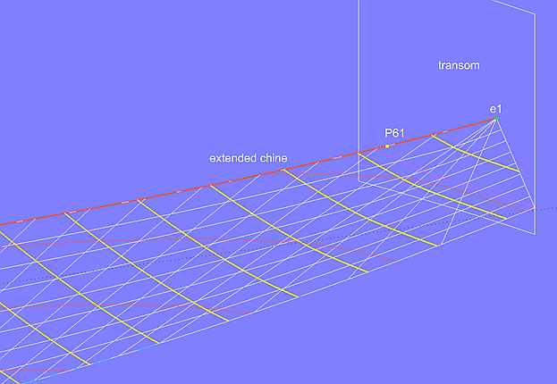
Model bottom_panel-4.ms2 - extension of the chine curve by a SubCurve entity
Method 3 - composite support curve
It is not required that the support curves of a developable hull surface run in longitudinal direction only. As shown in model bottom_panel_5.ms2, they can be combined piecewise in order to include the trailing edge of the surface. In this way, the curvature of sections can be controlled in this area.
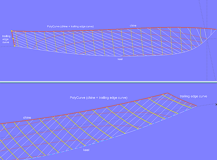
Model bottom_panel-5.ms2 - support curve as PolyCurve (composed of chine and trailing edge curve)
Partly straight run of a support curve
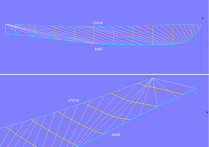
In case a support curve of the Developable Surface becomes straight, the unrolling plane will touch completely along the straight curve portion, and not just in a single point. This causes radially arranged rulings, resulting in unfairness. Model bottom_panel-6.ms2 shows an example. The bottom contour is a B- spline Curve, degree-3; its cps 4, 5, 6 and 7 are aligned, from cp5 on the bottom profile (keel) runs straight.
Model bottom_panel-6.ms2 - the bottom profile (keel) is straight aft. Combining chine and trailing edge makes the ruling arrangement more regular.
Combining chine and trailing edge makes the ruling arrangement more regular. And thus surface intersections (sections, waterlines, etc.) are more fair.
Support curve with inflection point
Should a support curve of a Developable Surface shows for design reasons an inflection point, for example the bottom profile of a powerboat, irregularities in the run of the rulings will arise – and as a result unfair waterlines, sections, buttocks. The model bottom_panel-7a.ms2 is an example for this.
Model bottom_panel-7a.ms2 – the inflection point of curve keel causes a non-uniform run of the rulings – sections become unfair.
In such a case the only remedy is to split the bottom surface into two patches. The front surface in model bottom_panel-7b.ms2 is developable (Developable Surface), the rear surface is a Ruled Surface. Often it must be only slightly forced into place during construction.
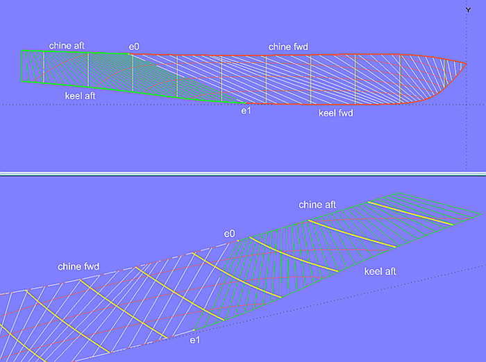
Model bottom_panel_7b.ms2 – bottom divided into two parts. Foreship is developable (Developable Surface), aftship is a Ruled Surface (requires some plastic deformation).
4 Hull design with developable surfaces
A boat with developable hull surfaces can only show a hull with one or more full length chines. Flat bottom boats, skiffs, scharpies are examples of chine hulls for sailing yachts, the V-shape is widespread with motorboats. It will be shown in the following, how typical hull shapes can be designed with developable surfaces.
4.1 Modern multichine hull
Model sy15_double_chine.ms2 is the chine hull version of the model sy15_full_chine.ms2 described in the tutorial "Round bilge hull with full length chine". The hull area below the topside surface consists of 3 Developable Surfaces. The lower support curve of the bilge surface chine_strake_2 is a B-spline Curve with 8 cps; it includes the rounding of the forefoot. In the bow area, the sections cutting this surface, are severely curved, due to the sloping rulings. The surface is bent across the rulings, and since these run obliquely to the direction of the sections, these are necessarily convex.
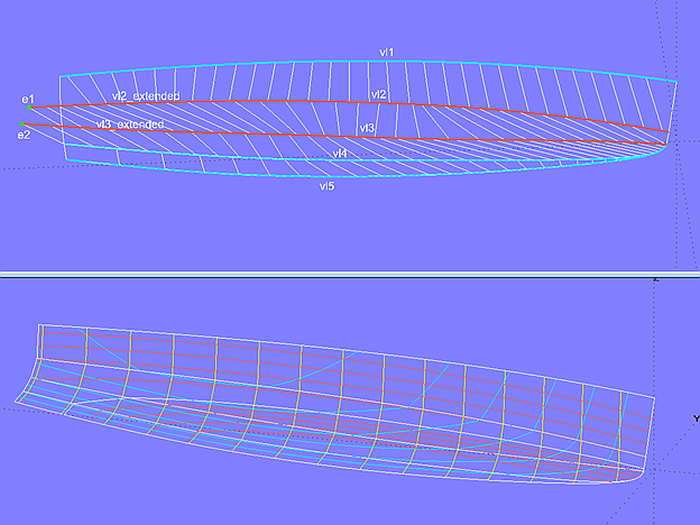
Model sy15_double_chine.ms2 - modern multichine hull. The upper support curves of the two bilge surfaces are each extended aft by SubCurves to achieve a uniform arrangement of rulings.
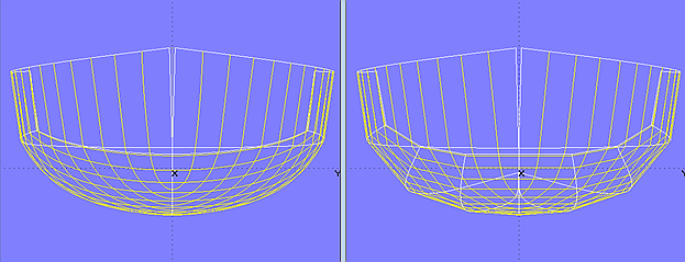
Body plan comparison - basic model sy15_full_chine.ms2 versus multichine version sy15_double_chine.ms2
4.2 Classic multichine hull
Model multi_chine_classic.ms2 shows a longkeel chine hull. At the stem the upper 4 panels extend beyond the midship plane to get a curved stem profile. The stem shape is therefore determined indirectly.
The end control points of the support curves are magnets on the transom surface.
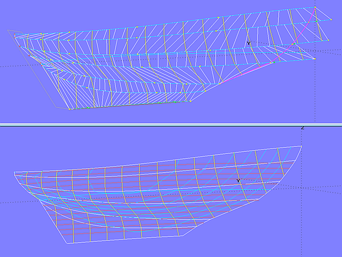
Model multi_chine_classic.ms2 - longkeel multichine hull
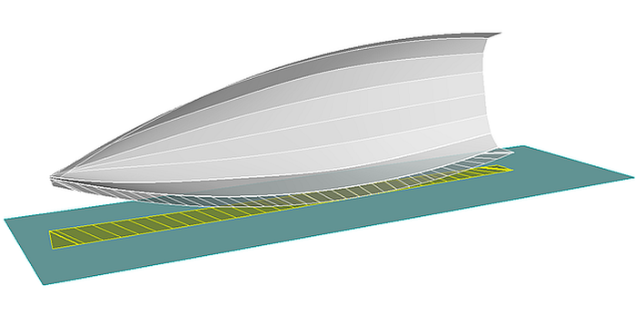
4.3 Powerboat
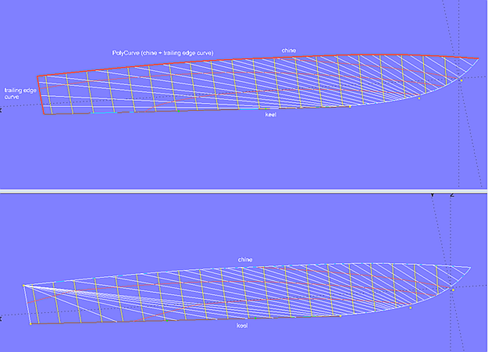
Model cruiser.ms2 features the hull of a powerboat (derived from a MultiSurf model from AeroHydro Inc.). Topside, bottom, bowround and transom are developable surfaces. For the lower support curve of the hull side (topside), the chine curve (chine) and the trailing edge (n1) are combined by the PolyCurve polychine1. The same applies to the bottom surface; here chine and trailing edge n2 are the components of PolyCurve polychine2.
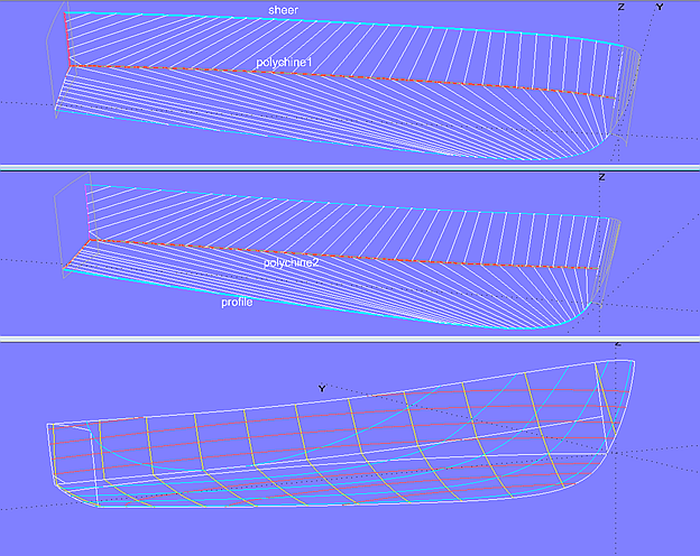
Model cruiser.ms2 - support curves for topside and bottom
The trailing edges of side and bottom are B-spline Snakes (n1, n2) on the transom base surface (transom_0), so there is no need to trim off any parts.
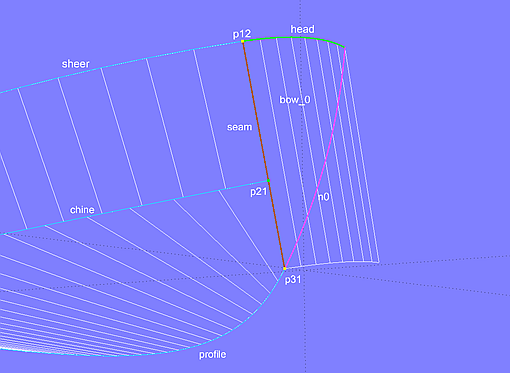
Model cruiser.ms2 - construction of the bowround
The base surface of the bowround is the Translation Surface bow_0, created by Line seam and the B-spline Curve head, the rounding of the upper edge of the hull (C-spline Curve sheer). Line seam connects the first cp (p11) of the hull upper edge and the first cp (p31) of the bottom profile (B-spline Curve profile). The first cp of the chine curve (chine) is a bead (p21) on Line seam, thus topside and bottom start along this line as well as tangential to the Translation Surface bow_0.
5 Special hull shapes
5.1 "Radius chine" hull
If one wishes to exploit the manufacturing advantages of developable surfaces but wants to avoid disadvantages by increased resistance, the "radius chine" hull form offers its service. First a single chine hull with developable surfaces for topside and bottom is designed. Then the bilge area is rounded off.
Method 1
In model radius_chine-1.ms2 the bilge rounding is a C-spline Lofted Surface with 4 B-spline mcs. Because a B-spline Curve begins tangentially to the line between its 1st and 2nd cp and ends tangentially to the line between its last but one and final cp, the smooth joint to side and bottom is built in firmly, if for cp1 and cp3 a bead on the line between sheer and chine respectively between chine and bottom is used. Example: the cps for mc2 are Bead e21, Point p22 and Bead e22. Bead e21 is on Line l2 between p21 and p22, so mc2 starts tangent to this one. Bead e22 is on Line l3 between p22 and p32, so mc2 ends tangent to l3.
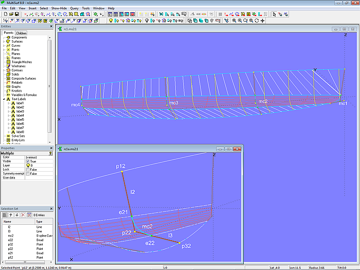
Model radius_chine-1.ms2 - rounding between the developable surfaces of topside and bottom by a C-spline Lofted Surface. The tangential joint of the mcs is hard-wired, e.g. at mc2 by Bead e21 on Line l2 and Bead e22 on Line l3.
Method 2
Model radius_chine-2.ms2 has a similar structure to model radius_chine-1.ms2, but for mc2, mc3 and mc4 the curve type Radius Arc is used. Example mc2: the arc starts tangentially to Line l2 between the Points p12 and p22 and ends tangentially to Line l3 between Points p22 and p23.
In this way the size of the round off radii can directly be specified by numbers.
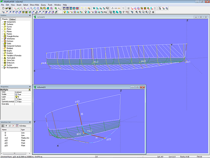
Model radius_chine-2.ms2 - master curves of type Radius Arc allow to specify the size of the round off radii directly by numbers.
Method 3
In the model radius_chine-3a.ms2 the bilge rounding is formed by a Rolling Ball Fillet. As the name implies, this type of surface can be thought of by a sphere that rolls between both surfaces and thereby surpasses a rounding, which extends between the path of all points of contact on the one surface and the path of all points of contact on the other surface.
In order to make the sphere touch, the bottom surface must extend beyond the centerplane; therefore its lower control curve runs on the negative side of the centerplane. In the bow also the topside must extend beyond the centerplane. Stem and bottom profile are thus the intersection of these basis surfaces with the centerplane (*Y = 0).
Model radius_chine-3a.ms2 - rounding between side and bottom by Rolling Ball Fillet (constant radius)
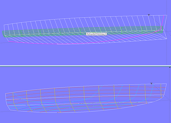
The radius of the Rolling Ball Fillet can be changed by a Graph entity. This is shown in model radius_chine-3b.ms2. Using the Graph h0 the radius of the Rolling Ball Fillet bilge_0 is at the bow half the radius at midships and at the stern twice the radius at midships.
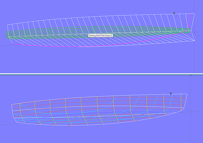
Model radius_chine-3b.ms2 - rounding between side and bottom by Rolling Ball Fillet (variable radius)
Which method to use for the bilge rounding on a radius chine hull depends on bounding conditions. In method 1, the rounding can be shaped freely, for example, as parabolas. With method 2 the rounding is always a circular arc. Values for varying radii must be chosen carefully to maintain fairness. In method 3, the rounding is a circular arc of constant or variable radius, but stem and bottom profile are indirectly defined; just one single entity is required for the bilge rounding.
5.2 Hull with non-developable surface patch
Developability means restrictions in design. The inner shape of the surface can only be influenced within narrow limits (via the run of the rulings). For example, with a Developable Surface it is not possible to create flared out foreship sections. If one does not want to renounce that, then the respective hull area must be modeled by a different surface type. The principle approach is demonstrated in model hardchine_powerboat.ms2.
First, the support curves involved (here sheer and chine1) are subdivided into two SubCurves. With the SubCurves sheer_aft and chine1_aft the Developable Surface topside_aft is defined. At its front edge the EdgeSnake n0 is then created. With the SubCurves sheer_fwd, chine1_fwd, the snake n0 and the bow curve stem the Tangent Boundary Surface topside_fwd is created (with tangency continuity along n0). If necessary its shape may be modified by internal control points.
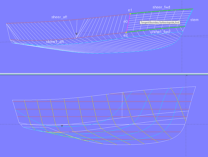
Model hardchine_powerboat.ms2 - the patch of the topside at the bow is not developable.
5.3 Hull with conical surface
Sometimes a chine hull should be formed by conical surfaces only. Model conic_bottom.ms2 shows this on the example of a bottom surface. Chine curve and the cone apex can be specified. However, the keel contour is not arbitrary, it can not be chosen freely, but results as the intersection of the conical surface with the centerplane. Thus the hull shape is subject to restrictions.
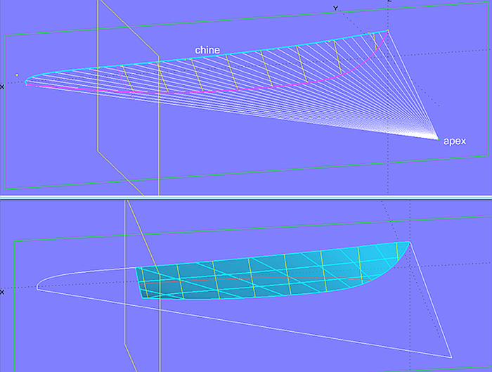
Model conic_bottom.ms2 - example of a hull bottom surface as part of a cone. The bottom profile results indirectly as centerplane intersection.
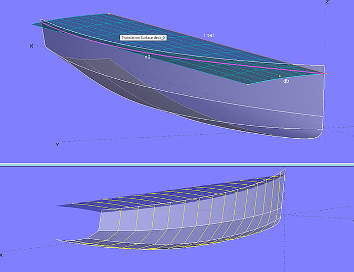
6 Deck with developable surface
Standard deck definitions generally result in surfaces that can not be rolled out flat (by bending only). Although superstructure and cockpit cut out large portions of the deck, what reduces the problem of necessary pre-forming, decks can also be designed using developable surfaces.
One way to create a developable deck is shown in model deck_devsurf.ms2. The Developable Surface deck_0 is spanned between the upper edge of the hull (EdgeSnake n0) and a deck beam at the stern (Arc db).
The price for the easier construction of a developable surface (only bending) is the restriction in form. The deck curve on centerplane straight, sections partly run straight too.
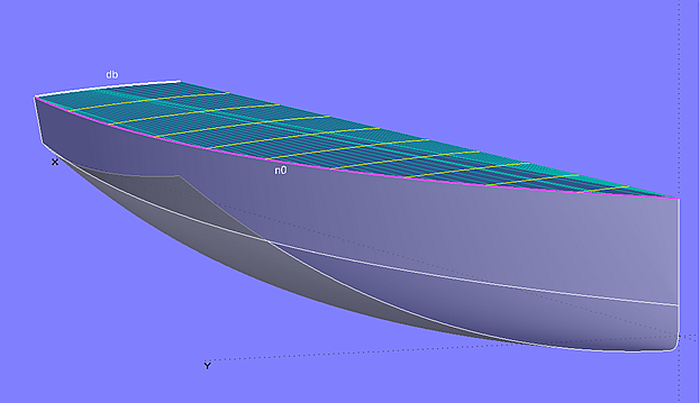
Model deck_devsurf-1.ms2 – Developable Surface spanned between top edge of hull n0 and deck beam db aft
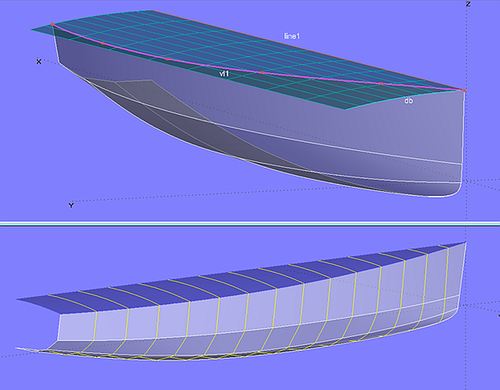
Another possibility is to use a circular cylinder for the deck surface. If the sheer edge of the hull claims priority, the deck needs to be lowered a bit, leaving a low bulwark or toerail. This is shown in model deck_devsurf-2.ms2.
The deck surface is a Translation Surface with Line line1 as generator and Arc db as guiding curve. Since the generator is straight, this translation surface is developable. It intersects the hull surface in the Intersection Snake n0.
Model deck_devsurf-2.ms2 - Translation Surface generated by line1 and deckbeam db as developable surface
If hull and deck edge should coincide, the upper support curve of the topside must lie on the deck surface. Because of this constraint the sheer curve is somewhat limited in shape. Model deck_devsurf-3.ms2 shows an example. If the sheer has considerable curvature in the foreship it can show an inflection point when the hull is viewed from aside.
Model deck_devsurf-3.ms2 - the upper support curve of the topside is a C-spline Snake on the developable deck surface.
7 Superstructure with developable surfaces
In the tutorial “Decks and Superstructures” there are several examples of how to model box-shaped superstructures. If their surfaces are of the type Translation Surface, where the generating curve is straight, they are developable. See the models trunk_cabin-1.ms2, trunk_cabin-2.ms2, trunk_cabin-3.ms2. Because in these models the guiding curve for the cabin roof is not straight, it must be replaced by a Line entity to make the roof developable. Although its profile on centerplane will no longer run curved, which may suffer aesthetics, but this is the price to pay for simple construction work.
Model conic_cabin.ms2 is another example. Cabin side and cabin front should be made from one single surface. For this a general conical surface is chosen. Its guide is the bottom edge of cabin side/front (B-spline Snake on the deck surface). The apex of the cone is positioned according to the desired slopes of cabin side and front. The cabin top is a circular cylinder. Trimmed Surfaces make the final surfaces of the superstructure.
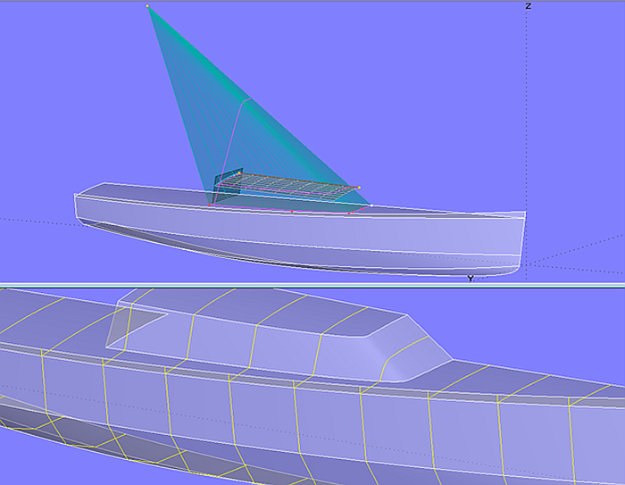
Model conic_cabin.ms2 – cabin side and front as part of a conical surface
8 Surface expansion
All developable surfaces can be expanded and exported as CAD files with the AeroHydro MSDev program or the MultiSurf add-on module Flattener. On the flattened surfaces there can be markings for bending lines, sections, waterlines, etc.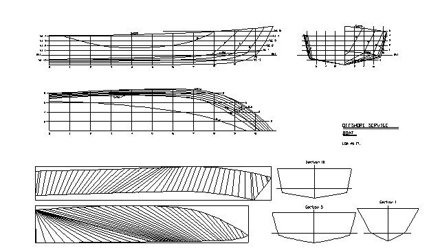
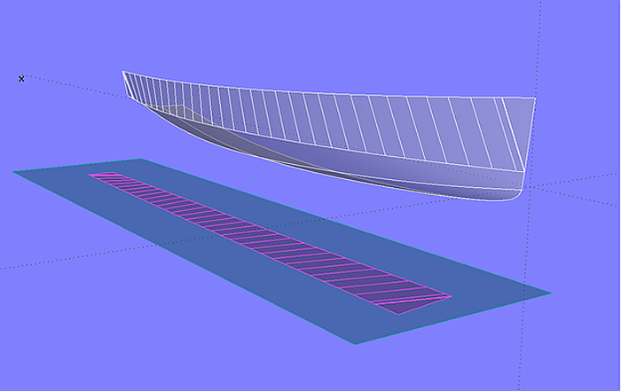
Expanded hull plates of a powerboat
Expanded Surface
If MultiSurf is authorized including the Flattener module, the surface type Expanded Surface is enabled. This allows surfaces to be expanded directly in MultiSurf.
Model expanded_surface.ms2 - surface flattening directly in MultiSurf with the surface type Expanded Surface
Transom Development
For ease of construction many boats feature a transom which is a portion of a circular cylinder. The model cyl_transom_expansion.ms2 explains how to construct the expanded shape of the transom within MultiSurf.
The Translation Surface transom_0 is the basis surface of the cylindrical transom. Its guiding curve is the Arc c1, generator is Line l1. The control points of both curves are defined in the 3-point Frame F1, so that one can rake and shift the transom without changing its shape.
Hull and deck are intersected by the surface transom_0 in the Intersection Snakes n1 and n3, which in turn are projected onto transom_0 as Projected Snakes n2 and n4.
The expansion of the transom basis surface is the Translation Surface s0, whose guiding curve is the Line l2 (end point is Point pt3), the generator is again Line l1. The length of Line l2 must be equal to the length of the Arc c1. Since s0 is in the XZ plane of the Frame F1, the Z-coordinate of Point pt3 (end point of Line l2) simply corresponds to the length of c1. This length is displayed in Tools/ Mass Properties.
When the arc is changed, for example, to increase the camber of the transom, the position of pt3 must be adjusted manually.
To avoid this, the simple Formula f1:
f1 = ARCLEN (c1, 0, 1)
which calculates the length of Arc c1, is used for the Z-coordinate of pt3. In this way it is guaranteed, that s0 always is just as long as Arc c1.
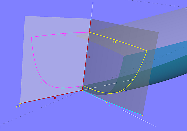
Model cyl_transom_expansion.ms2
In order to get the developed shape of the transom on s0, the two Projected Snakes n2 and n4 are copied onto s0 as Copy Snake entities. Since s0 is in the centerplane, the profile view of the model (Y-view) shows this outline in real size. Alternatively, View/ Modify/ Set View/ Normal to ... also provides the vertical screen view (select s0 beforehand). The view can be exported then via File / Export 2D / DXF.
In this way the true outline of the circular cylinder transom is constructed without a specialized program.
======================================================================================