Components
Part 1 – Basics and Examples
by Reinhard Siegel
October 2021
Contents
Introduction
Basics – component Winch
Editing of components in the Entities Manager
Component Transom
Component Keel
Component Longitudinal Frame
Component Main Dimensions
Templates for hull plate forming
Possible component problems
Modifying a component file
Introduction
No design looks like the other. But boats, yachts and ships are similar. With components one can save time and effort. A component is a piece of coherent MultiSurf geometry that can be inserted into other models. Instead of creating in the work model the prefered construction for keel, rudder, deck, transom etc. each time entity by entity, they can be inserted with little effort using components.
With components, the structure of a model can be clearly arranged. A component can be used to detach a related group of entities from a large model, edit it in a separate model and insert it into other models.
This tutorial is aimed to explain how to load components into a model, how to create them, which tools are available. In part 1 the tutorial will introduce a number of components that are practical when building the geometry model of a boat. Part 2 will show numerous components to give models a realistic appearance.
Abbreviations used:
cp: control point (support point)
mc: master curve = support curve
cp1, cp2, ...: denotes 1st, 2nd, ... point in the list of supports of a curve. It is not an actual entity name.
mc1, mc2, ...: denotes 1st, 2nd, ... curve in the list of supports of a surface. It is not an actual entity name.
In the following the terms used for point, curve and surface types are those of MultiSurf. This may serve the understanding and traceability.
Basics – component Winch
Component source model
As an introduction to the topic of components, let us consider the model winch-model.ms2. It contains the geometry of a simple winch. Magnet m0 is on the base surface s0; Offset Point p0 and Point p1 depend on it. With m0, p0 and p1 the 3-point Frame F is defined. In this user-defined coordinate system the points are created which determine the cross-sectional curve c0. This in turn is rotated around Line l0, which yields the Revolution Surface s1. If Magnet m0 is moved, the winch moves with it. The axis of rotation is always perpendicular to the base surface.
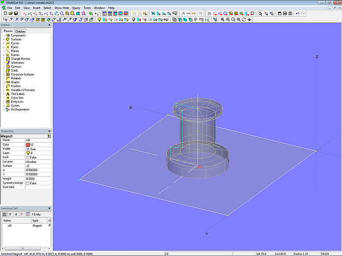
Model winch-model.ms2 – winch as Revolution Surface in the source model
Winch-model.ms2 is not a component, but a normal MultiSurf model file (extension of the filename is ".ms2"). It is the source model for the winch component. A component file has the extension ".mc2".
Saving the component
In general, a component needs parents from the host or working model, the model into which it will be inserted. In our example, the surface s0 on which the Magnet m0 is situated, will be replaced by a surface in the working model when the component is loaded. So let us select the magnet m0 in the first step.
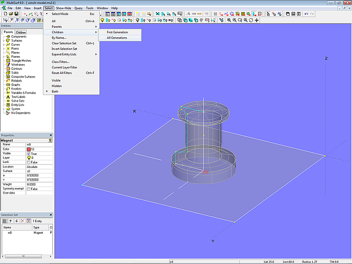
Model winch-model.ms2 – selection of all entities of the winch geometry depending on Magnet m0
And then in the second step, everything that depends on it: Select/ Children/ All Generations. All entities that depend on m0 are now in the Selection Set, i.e. the entire winch construction.

Model winch-model.ms2 - entities of the winch geometry dependent on magnet m0 in the source model
Now select File/ Component/ Save in the main menu, whereupon the following dialog box will open:
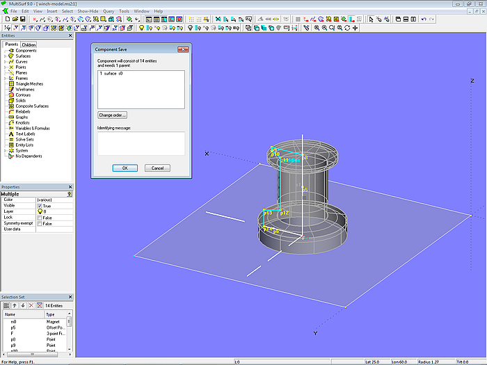
Model winch-model.ms2 – saving the winch component in the source model
The model into which the winch component is to be loaded (host model, work model) has to provide a surface. Finally click the OK button and save the component under the name winch-component.mc2.
Loading the component
Let us try out how to insert the component into another model. Open the model boat-0.ms2. It contains a hull surface (hull_0) and a deck surface (deck_0). Then File/ Component/ Load and in the dialog window select the component file winch-component.mc2. Now the dialog box “Load Component: Resolving Parents” will appear. Its purpose is to select the parents to whom the component is connected when inserting it into the work model.
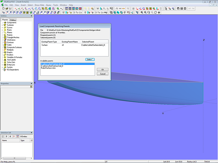
Model boat-0.ms2 – parent selection when loading the winch component into the work model
In this example, it is the deck surface deck_0 that replaces the surface s0 from the source model.
After confirming with OK the dialog box "Load Component: Resolving Names" is displayed. It is used to give the component a name in the host model and resolve naming conflicts. In our example, the component is given the name "winch". This string is prefixed to all entities that are inserted by the component. By using this name there are no entity name conflicts.
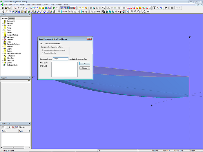
Model boat-0.ms2 – entering the name of the winch component when loading into the work model
After confirming with OK, the winch appears on the deck surface. With Magnet winch.m0 can be moved to the desired position.
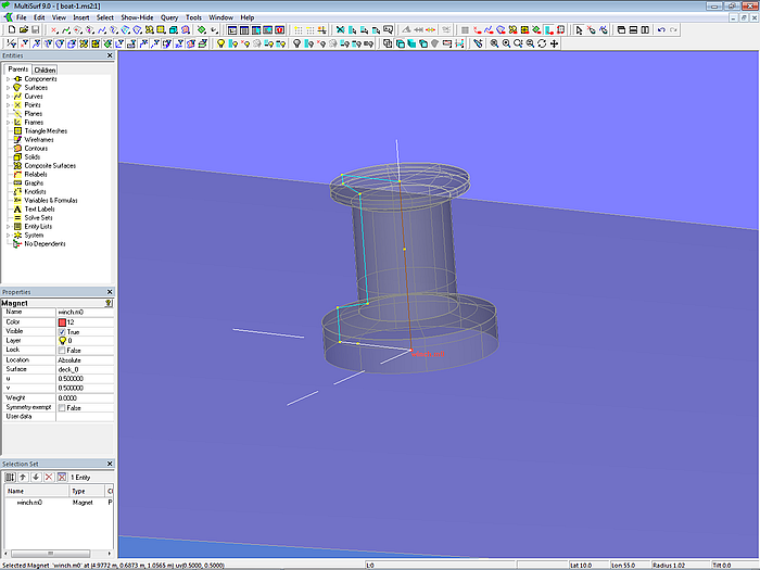
Model boat-1.ms2 – component winch added to the work model
Now save the model using the filename boat-1.ms2.
Editing of components in the Entities Manager
In the Entities Manager the top category is "Components". Here components are listed under the names assigned at loading. “Components” by itself features a context menu.
Function mouse right click on "Components"
If you click with the right mouse button on "Components", a context menu with 2 options is displayed:
Load – load a component (alternative for File/ Component/ Load)
Change order – change the order in which components are displayed in the Entities Manager
Function mouse right click on the name of a component
There is another context menu. If you click with the right mouse button on the name of a listed component, the following options are available:
Select – selects all entities of the component; practical for query purposes, layer modification
Delete – deletes all entities of the component and removes it from the Entity Manager
Show – sets the property "Visible" of all entities of the component to "True"
Hide – sets the property "Visible" of all entities of the component to "False"
Make internal – it can sometimes be useful to include a component in the main body of the host model. For example if prefixes should be removed or if a little construction component was added which should not be separated from the model with its own headline. Make internal removes all prefixes and deletes the component designation. Possible name conflicts can be resolved with the help of a special dialog window.
Current – a current component is similar to a current layer. All subsequently inserted entities are added to the current component.
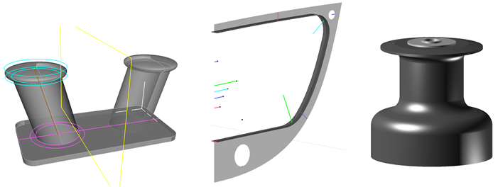
Component Transom
We now want to create the geometry for another component, save it as a component and then load it into the model boat-1.ms2. The component should represent a circular cylindrical transom.
Transom source model
The model transom-model.ms2 serves as the starting model. It contains the hull surface hull_0 and the deck surface deck_0. Also there is the base surface of the transom, transom_0. This is a Translation Surface with curve c0 (Arc) as guide and Line l0 as generator. All points for c0 and l0 are defined in the 3-point Frame F. For its part, F is determined by Point xt (origin of the frame on the X-axis), Point rake (length and inclination of the centerline of the transom surface) and Point p1 (abeam of xt).
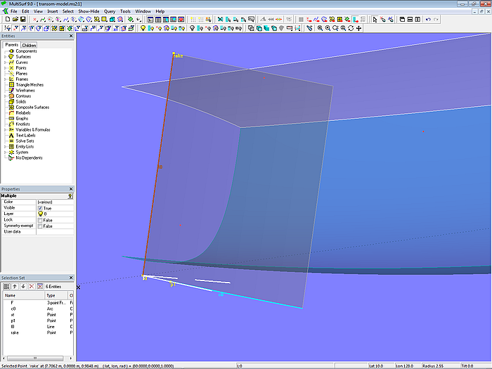
Model transom-model.ms2 – the base surface transom_0 of the circular cylindrical transom is created by moving Line l0 along Arc c0.
The transom base surface transom_0 intersects the hull surface hull_0 in the Intersection Snake n0. Likewise it cuts the deck surface deck_0 in the Intersection Snake n2.
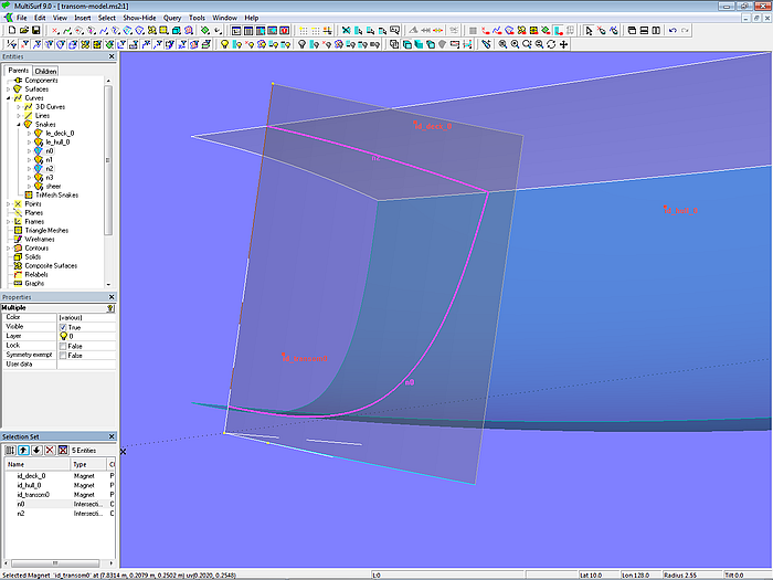
Model transom-model.ms2 – transom base surface transom_0 cuts hull and deck in the Intersection Snakes n0 and n2.
Both snakes are projected onto the transom base surface as Projected Snakes n1 and n3. The final transom surface is then created with these two snakes by Trimmed Surface transom.
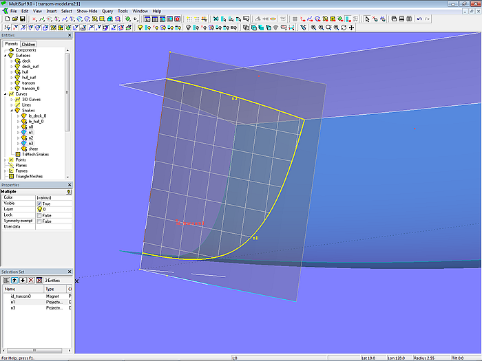
Model transom-model.ms2 – final transom surface (Trimmed Surface transom) in the source model
Next two Entity Lists are created. The Entity List parents contains the surfaces hull_0 and deck_0. The Entity List products just holds the Trimmed Surface transom. The purpose of these lists is explained in the following section.
Finally the source model of the transom component is saved as transom-model.ms2.
Saving the component Transom
Command SelectForComponent – the perfect tool for creating a component
We now want to save the transom model as a component. The host or work model, i.e. the model into which the component is to be inserted, must provide a hull and a deck surface (parents of the component). So we have to select all entites, that create the final transom surface, but not these two surfaces. If we were to select hull and deck and then, as in the case of the winch component use again Select/ Children/ All Generations the Selection Set would possibly contain dependent entities (children) of these surfaces, which have nothing to do with the transom, such as the Contours dwl_0, buttock_0 etc., which are also included in the source model and depend on deck and hull. Though momentarily hidden, those would also be selected.
If the source model is specially made for the creation of a component and as with the Winch component only requires a single parent from the host model, the easiest way for selection is via Select/ Children/ All Generations. But if you want to extract a component from a large geometry model or select entities for a component that requires more than one parent from the host model it quickly becomes complicated, because you always have to consider all dependencies in order not to include parents you do not want.
To simplify the selection process, there is the command SelectForComponent in MultiSurf. It is extremely useful when creating components. Because it selects the minimum set of entities required in order to generate the entities in the Entity List "products" for the parents specified in the Entity List "parents". The SelectForComponent command selects all necessary component entities fast and effectively.
So let us now select the two Entity Lists parents and products and enter the command SelectForComponent via Tools/Command Window.
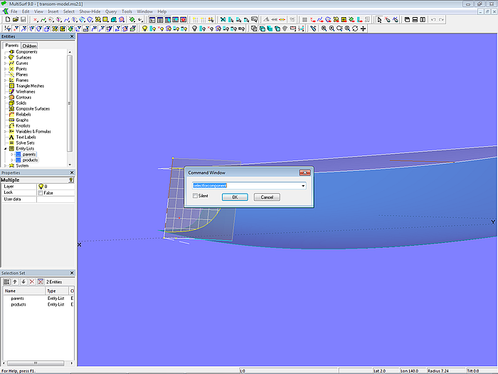
Model transom-model.ms2 – selection of the component entities via the command "SelectForComponent" in the source model
After OK, the Selection Set Manager then contains all the entities required for the transom component.
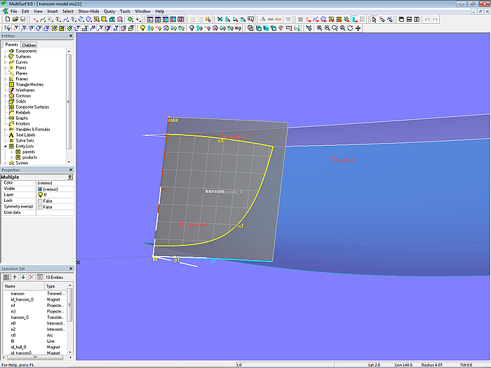
Model transom-model.ms2 – entities of the transom component selected via the command “SelectForComponent” in the source model
It continues with File/ Component/ Save. The "Component Save" dialog box appears showing which parents the component expects from the host model.
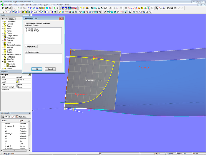
Model transom-model.ms2 - the transom component requires 2 parents in the work model
Then hit OK and save the transom component under the name transom-component.mc2.
Loading the component Transom
Now let us load the transom component into the work or host model boat-1.ms2. Open this model and then via File/ Component/ Load select the component file transom-component.mc2 and open it. Or alternatively right-mouse click on “Components” in the Entities Manager and from the context menu choose “Load”.
In the window "Load Component: Resolving Parents" select the corresponding surfaces, to be used by the component. OK then.
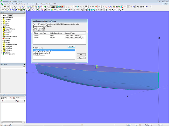
Model boat-1.ms2 – selection of parents when loading the transom component into the work model
In the "Load Component: Resolving Names" window enter the name of the component: transom, then OK.
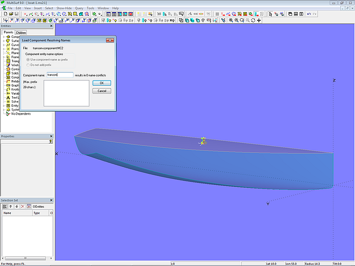
Model boat-1.ms2 – when loading the transom component into the host model it is given the name transom
Now the entities of the transom component are displayed, but also an error message.
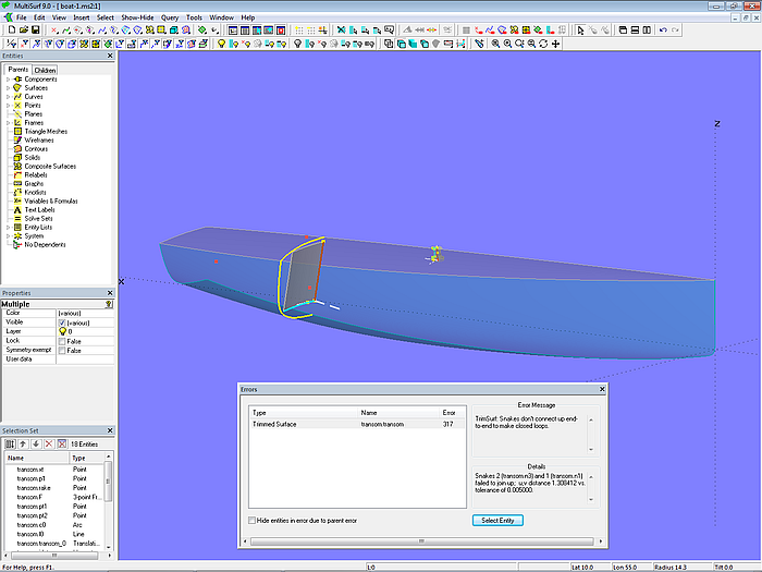
Model boat-1.ms2 - the transom component causes an error message.
The reason for the error message is easy to see: the base surface transom.transom_0 is too small both in width and height, and it is also located pretty far ahead. Because the hull surface in the source model from which the component was saved (LOA = 8 m), is smaller than the hull surface in the host model in which it is loaded (LOA = 10 m).
What do you have to do? Only move Point transom.xt in the area of the aft overhang, and with Points transom.pt2 and transom.rake adjust width and height of the base surface transom.transom_0 to hull and deck.
Then save the model as boat-2.ms2.
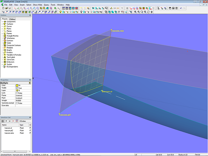
Model boat-2.ms2 – final circular cylindrical transom after adjusting base area in the work model
So much for the transom component.
Component Keel
Keel source model
Starting point is the model keel-model.ms2. It contains a keel appendage consisting of fin and ballast-bulb as well as a fillet between the two. The root section of the fin on the X-axis is formed by the Foil Curve root_0, defined with the Points ip (leading edge), pt2 (root section thickness) and pt3 (trailing edge). The root section on the hull surface is created by the Projected Snake root. The Foil Curve tip determines the tip section, defined with the points pt4 (leading edge), pt5 (tip section thickness) and pt6 (trailing edge). Between curves root and tip the Ruled Surface fin_0 is spanned as the base of the fin surface.
The ballast bulb is a Revolution Surface. Meridian is Foil Curve bulb_meridian, determined with Points pt4 (leading edge), pt7 (thickness) and pt8 (trailing edge). Axis of rotation is Line bulb_axis between pt4 and pt8.
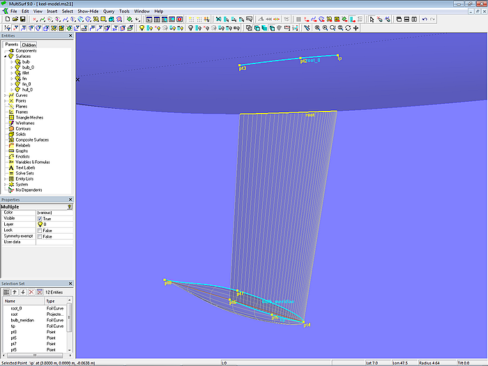
Model keel-model.ms2 – basic entities of fin and bulb construction in the source model
The rounding between fin and bulb is the Blend Surface fillet. It requires 4 snakes, two on one surface and two on the other. B-spline Snake n1 determines the start of rounding on the fin. Intersection Snake n2 is the cut of the fin surface by the bulb. In turn, it is then projected on the bulb surface as Projected Snake n3. The run-out of the rounding on the bulb defines the B-spline Snake n4.
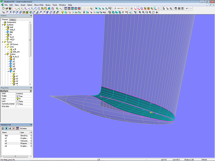
Model keel-model.ms2 - rounding between fin and bulb with Blend Surface
The surface portion from the fin root to the beginning of the rounding fillet is the SubSurface fin, Trimmed Surface bulb is the portion of the bulb minus the rounding.
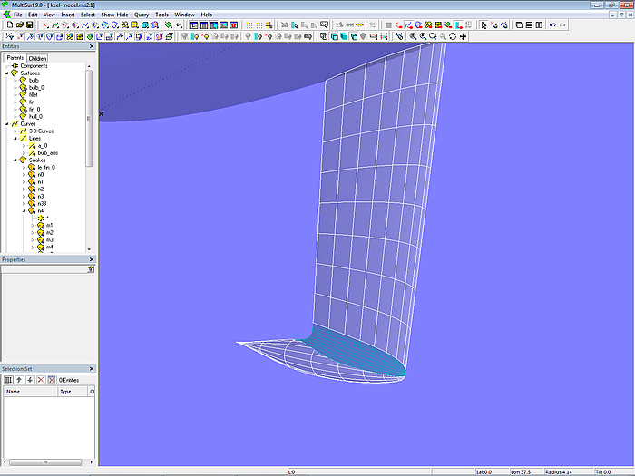
Model keel-model.ms2 – final keel surfaces in the source model
Saving the component Keel
It is useful before saving a component to show only its essential surfaces, handles and cps, but every-thing else is hidden. After inserting the component the work model will be clearer and the component geometry easier to change, if only that entities ultimately relevant for the shape are displayed.
With the two Entity Lists parents and products and the command SelectForComponent now all entities for the component geometry are selected and the result is saved via File/ Component/ Save. The “Component Save” dialog box will show which parents must be provided by the host model.
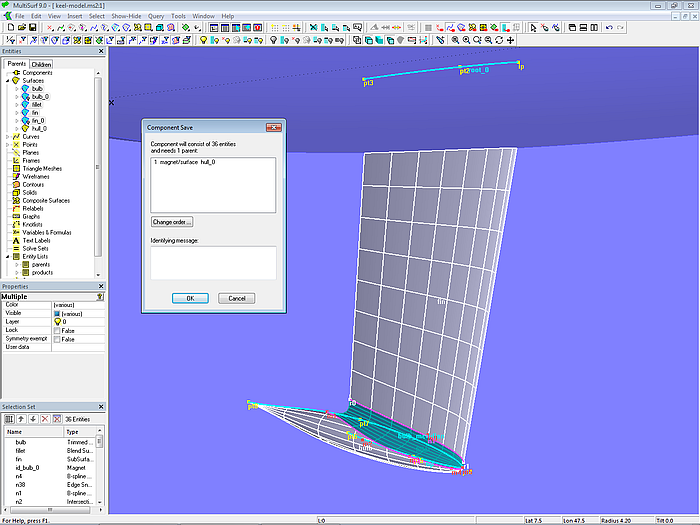
Model keel-model.ms2 - selected entity set for the keel component in the source model
Then OK and save the keel component using the name keel-component.mc2.
Loading the component Keel
Now we want to load the keel component into the boat-2.ms2 model, our work model. Open this model, then load the component file keel-component.mc2 via File/ Component/ Load or the “Components” context menu in the Entities Manager.
In the "Load Component: Resolving Parents" window select the corre-sponding parent surface (hull_0), then OK.
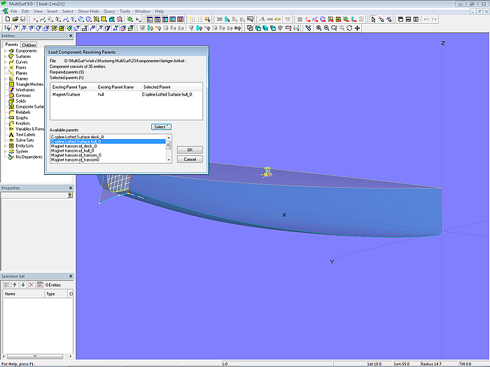
Model boat-2.ms2 – selection of parent when loading the keel component into the work model
In the "Load Component: Resolving Names" window now enter the name of the component: keel. OK then.
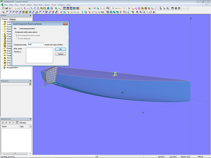
Model boat-2.ms2 – when loading the keel component into the host model it is given the name keel.
Then save the model as boat-3.ms2.
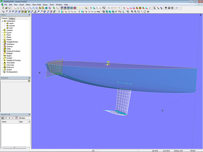
Model boat-3.ms2 - component keel loaded into the work model
So much for the keel component.
Component Longitudinal Frame
If the plating of a metal hull is stiffened with longitudinal frames, there are typically several of them. Instead of constructing several longitudinal frames entity by entity again and again in the same way, a component saves time and work.
Source model Longitudinal Frame
The construction of a longitudinal frame is rather easy. For this let us consider the geometry model lon_frame-model.ms2. The surface itself is a Sweep Surface. For its construction a path is needed, a cross-sectional shape of the frame, and a curve that determines its twisting.
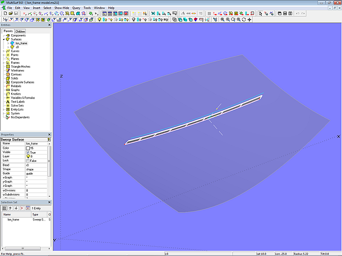
Model lon_frame-model.ms2 - source model of the component for a longitudinal frame
Because the path will be the parent of the component provided by the host model, so that is why in the source model the simple Line Snake path is sufficient. First the Ring r0 is generated on the path for the longitudinal frame (path). Then the Tangent Point pt1 and the Offset Point pt2 are inserted, both dependent on r0. With these three points the 3- point Frame F is determined. In this coordinate system points are defined to control the shape of the frame cross-section represented by the B-spline curve shape (Degree = 1). Here in our example, the cross-section is a simple rectangle, but other shapes are easy to model.
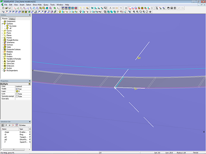
Model lon_frame-model.ms2 - coordinate system for frame cross-sectione
The longitudinal frame is modeled by the Sweep Surface lon_frame. To make sure that everywhere the cross-section is perpendicular to the hull surface, the Sweep Surface uses as support the curve guide, being an Offset Curve to the Line Snake path.
Saving the component Longitudinal Frame
With the two Entity Lists parents and products and the command SelectForComponent now get the entity set for the component geometry, then save the result via File/ Component/ Save in the component file lon_frame-component.mc2.
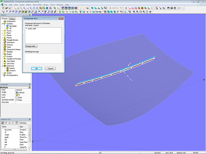
Model lon_frame-model.ms2 – saving the set of entities for the component
Loading the component Longitudinal Frame
As in the previous examples, the longitudinal frame component should now also be loaded into a work model. Let us use for this the model boat-3.ms2.
In this model there is for the path of the component the UVSnake n1, determined by Magnet m0. Of course this is a simple construction, with little control on the run of the path. Should the path run in a diagonal plane or a buttock plane, the hull surface must be intersected with a corresponding plane (Intersection Snake). To free-form the path, one can use a C-spline or B-spline Snake with several cps (magnets, rings). Or a C-spline Curve supported by magnets/rings is projected onto the hull surface (Projected Snake), whereby the influence of its u/v-parameter curves on the run of the snake is canceled.
The longitudinal frame component is loaded in the same way as in the preceding examples (component name: ls1). Then save the work model as boat-4.ms2.
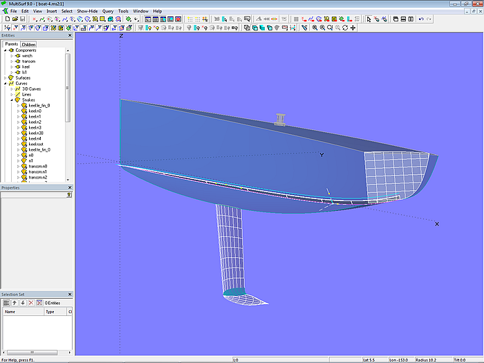
Model boat-4.ms2 - longitudinal frame component ls1 inserted
The component presented can be modified easily for the construction of other components, for example, a longitudinal deck frame. To keep the cross-sections of the Sweep Surface vertical, the Offset Curve guide can be replaced by a Copy Curve.
Component Main Dimensions
In tutorial 14, “How to Create Computing MultiSurf Models”, the model main_dimensions.ms2 is discussed. The model determines the main dimensions of a boat hull. With the help of a component, the calculation methods can be inserted into other models.
Main Dimensions – source model
The basic model for this component is model main_dim-model.ms2. The necessary formulas use essentially the functions XPOS, YPOS and ZPOS in order to determine the XYZ coordinates of points. With these coordinates distances are calculated, for example, length over all, waterline length, front and rear overhang, etc.
Maximum deck width and beam of waterline are found with the help of Proximity Rings. This entity automatically finds the point on a curve that has the greatest distance from a plane (here midship plane).
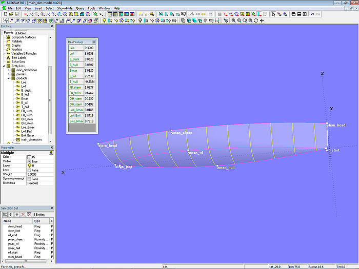
Model main_dimensions.ms2
Saving the component Main Dimensions
Entity List parents holds the boat surface hull, while Entity List products contains all formulas needed for the calculation of the main dimensions. As with the components already described, all required entities for the component geometry can be easily selected with these two Entity Lists and the command SelectForComponent. Then save the result via File/ Component/ Save (filename main_dim-component.mc2).
Loading the component Main Dimensions
Open the model boat-4.ms2 as work model and add the component main_dim-component.mc2 via File/ Component/ Load or the “Components” context menu. The component requires as parent just a surface, to do this, select hull_0 accordingly. Component name: dim. Finally save the model file as boat-5.ms2.
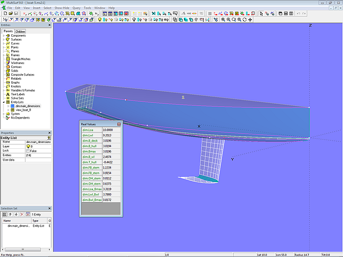
Model boat-5.ms2 – component dim for calculation of the main dimensions added
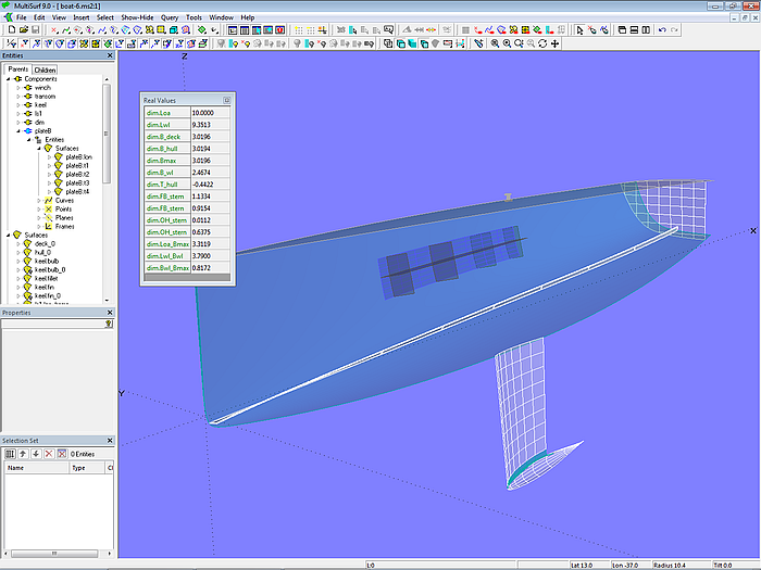
The numerical values of Variable and Formula entities can be displayed in MultiSurf via Tools/ Real Values (main menu), or simply press the V key as short-cut. To avoid that the values of all formulas and variables in a model are displayed, it is advisable to add only the desired values into an Entity List. Select it in the Entities Manager, then V. The inserted component contains the Entity List dim.main_dimensions.
Templates for hull plate forming
When building metal boats and ships, the outer shell consists of a set of plates. In the case of a round-bilge hull shape, plates are curved in all directions and must be brought into their 3-dimensional shape by a forming process. To control the forming, templates for the hull shape in the area of a plate are helpful. With a component, these templates can be created for each single plate with little effort. Let us consider the model templates-model.ms2.
Templates source model
Model
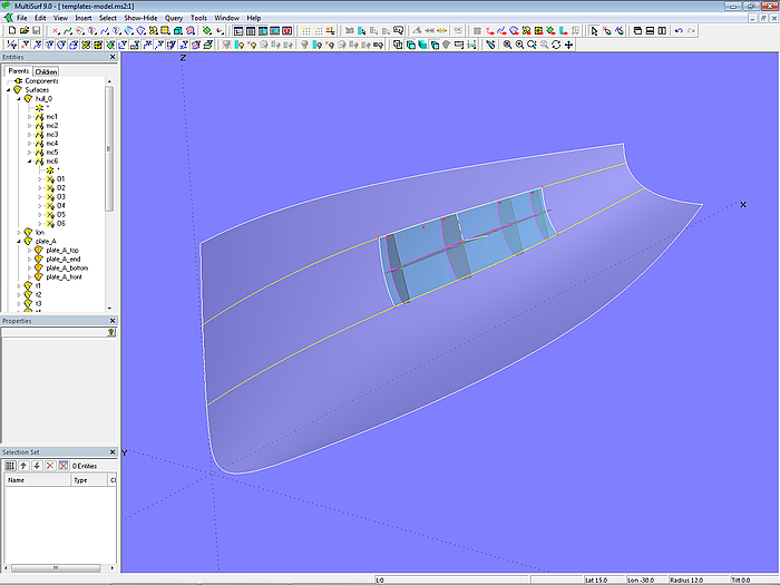
Model templates-model.ms2 – source model for templates to control the forming process of shell plating
The transverse templates are at right angles to the lengthwise template, their back edges are in a common plane. Placed on a flat ground, the free template edges describe the shape of the SubSurface plate_A.
The starting point of the construction is Magnet m on plate_A. On it depends the Offset Point p_off and the Magnet m_rot which is relative to m. With these 3 points the 3-point Frame F is defined. Point p_x lies on the X-axis of F, Point p_y on the Y-axis, and Point p_z on the Z axis. There is also Line l0 between Magnet m and Point p_x. Line l0 is support for the Arc-length Bead height, with which the height of the templates is determined.
With p_x, p_y, p_z and the Magnet m 3 planes are created as 2-point Plane entities: plan_lon perpendicular to the Z-axis of frame F, plan_trans perpendicular to its Y-axis, and plan perpendicular to its X-axis.
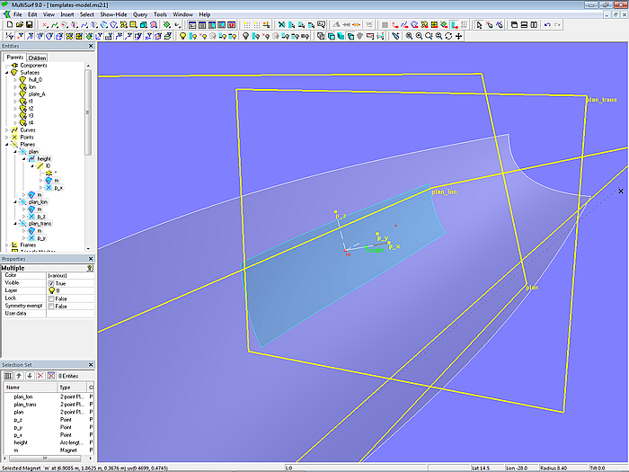
Model templates-model.ms2 - projection and section planes for longitudinal and transverse templates
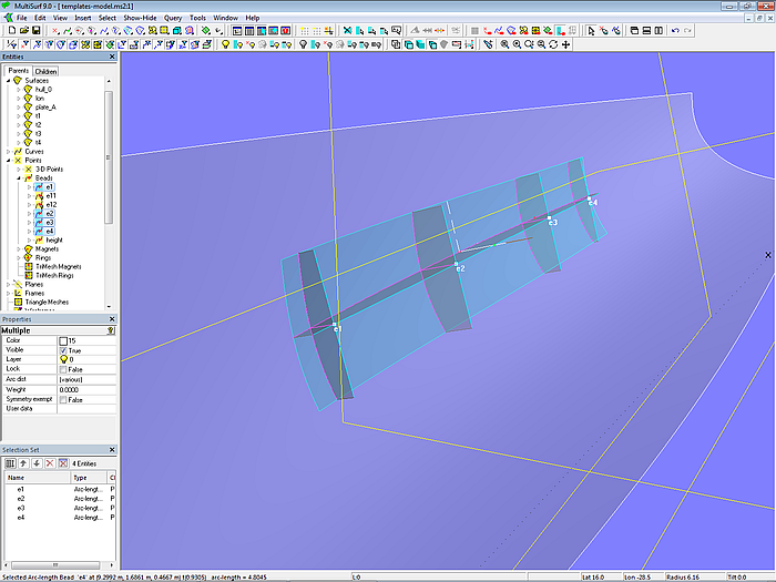
The 2-point Plane plan_lon now cuts plate_A in the longitudinal direction in the Intersection Snake n_lon. This in turn is projected onto the 2-point Plane plan as Projected Curve proj_lon on which the 4 Arc-length Beads e1, e2, e3 and e4 are situated. At their positions plate_A is now cut by the 2-point Plane plan_trans in the Intersection Snakes n1_trans, n2_trans, n3_trans and n4_trans. They are also projected onto plan.
These intersection snakes and their projections are then used to create the longitudinal template and the 4 cross templates as Ruled Surfaces (t1, t2, t3, t4, lon).
The templates can be easily adapted to the respective conditions of the shell plate for which they are intended. With Magnets m and m_rot the longitudinal template can be moved and rotated so that it runs nearly in the middle of the plate. With beads e1, e2, e3 and e4 the transverse templates can be distributed lengthwise, the Arc-length Bead height adjusts the height of the templates.
Model templates-model.ms2 - source model for templates for the control of the forming of hull shell panels
So much for the construction of the source model for the template component.
Saving the component Templates
It is useful before saving a component to show only its essential surfaces, handles and cps, but every-thing else is hidden. After inserting the component the work model will be clearer and the component geometry easier to change, if only that entities ultimately relevant for the shape are displayed.
Entity List parents only holds the SubSurface plate_A, while Entity List products contains the 5 template surfaces. With both Entity Lists and the command SelectForComponent the component entities set is selected and then saved via File/ Component/ Save (filename templates-component.mc2). The source model templates-model.ms2 can now be closed.
Loading the component Templates
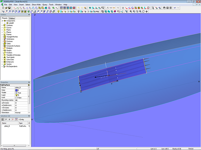
Now let us add the component to the model boat-5.ms2, which will serve as our host model. So open this model, show the SubSurface plate_B and select it. Then File/ Component/ Load or “Components” context menu; as component name choose plateB. The names of all the inserted entities will get this string as prefix and you can identify to which plate the templates belong to. Finally save the model under the filename boat-6.ms2.
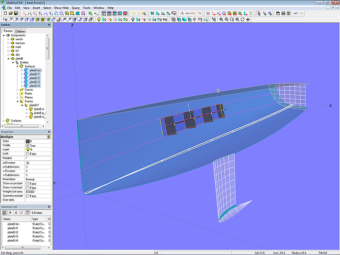
Model boat-6.ms2 - component plateB for plate templates added
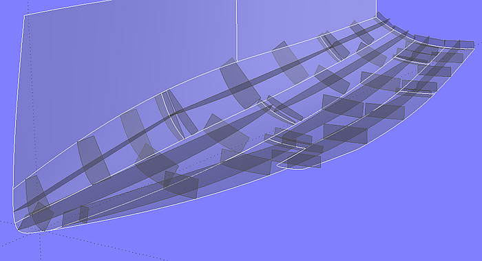
Application of the template component – 13 m sailing yacht
Possible component problems
A component is a piece from a MultiSurf model. Its dependencies are usually incomplete; it needs parents from the host model (working model) into which it is inserted. This is why source model and host model should match in the following ways:
- Similarity of parents
- same normal direction for surfaces
- same u/v-parameter direction for surfaces
- same t-parameter direction for curves and snakes
If there are differences, errors can occur when loading a component. In general, however, they are easy to fix.
Similarity of source and host parents
The parents of the host model must match those in the source model. For example, if in the source model the component is a C-spline Lofted Surface with 3 master curve parents, in the host model the parents for the component must be 3 entities that qualify as curves (curve, snake, point).
Same normal direction for surfaces
In model boat-1.ms2 the normal orientation of the deck surface (deck_0) is upwards. The winch is on the deck. Would deck_0 be oriented inside, the winch would be upside down. That is easy to correct in that the value for "Offset" of winch.p5 is given an opposite sign. Though you could also use the Entities Manager to set the "Orientation" property of deck_0 from “Normal” to “Reverse”, you should refrain from doing this because other entities could be affected. If you only edit the component, the effect remains limited to its entities.
Same u/v-parameter direction for surfaces
Let us consider the example boat-6a.ms2 into which the template component is loaded. In contrast to the model boat-6.ms2, the u-parameter direction runs in the transverse direction of SubSurface plate_B. Correspondingly, the templates are twisted.
With Magnet plateB.m_rot they can simply be turned around into the desired direction.
Difference in size between component source model and host model
This is the case, for example, with the transom component described above. It was saved from the model for a smaller boat and then was loaded into a model for a longer boat.
Model boat-6a.ms2
Modifying a component file
When MultiSurf saves a component file (* .mc2), all parents of the component from the source model are included as hidden entities. That is why a component file (* .mc2) can also be opened independently in MultiSurf. From main menu select File/ Open, and then in the “Open”-dialog window choose in the input field at the bottom right “All files (*.*)".Now the selection window will list not only standard model files (* .ms2), but also component files (* .mc2).
In this way you can edit a component file in the same way as a normal model. You can then save it as a model file (.ms2), or create a modified component (.mc2).
Model boat-6.ms2 – example model with 6 components added
So much for part 1 of the tutorial about models for components, storing components and loading components into other models.
Part 2 of the tutorial will introduce a number of components for equipment details to give a boat or ship a more realistic appearance in Render View.
======================================================================================