Three Modeling Exercises
Catamaran hull, multi-concave hull bottom, Swath Ship: pod - strut transition
by Reinhard Siegel
May 2022
Content
Introduction
1 Catamaran hull
1.1 Shape features
1.2 Hull outside surfaces
Top edge of side
Lower edge of bottom
Forward edge of side and bottom
Trailing edge of side and bottom
Inner master curves
Surfaces
1.3 Hull inside surfaces
Bottom
Side
2 Multi-concave hull bottom
2.1 Shape features
2.2 Hull with standard bottom
Top edge of side, chine, bottom contour
Stem - leading edges of side and bottom
Trailing edges of side and bottom
Inner master curves
Hull surfaces
2.3 Hull with multi-concave bottom
Master curves - rule-based approach
Master curves - free-form approach
3 Swath ship: pod-strut transition
3.1 Shape features
3.2 Base model
3.3 Rounding 1 – Rolling Ball Fillet
3.4 Rounding 2 – Blend Surface
3.5 Application – Swath Ship
Model construction
Hull surfaces
Buoyancy body and strut
Transition pod – strut
Introduction
This tutorial, inspired by a MultiSurf user, is about modeling the geometry of a catamaran hull, a multi-concave bottom of a powerboat and the transition between two surfaces. It deals with the creation of characteristic form features, to generate models with specific main dimensions is not the purpose.
Abbreviations used:
cp: control point (support point)
mc: master curve = support curve
cp1, cp2, ...: denotes 1st, 2nd, ... point in the list of supports of a curve. It is not an actual entity name.
mc1, mc2, ...: denotes 1st, 2nd, ... curve in the list of supports of a surface. It is not an actual entity name.
In the following the terms used for point, curve and surface types are those of MultiSurf. This may serve the understanding and traceability.
1 Catamaran hull
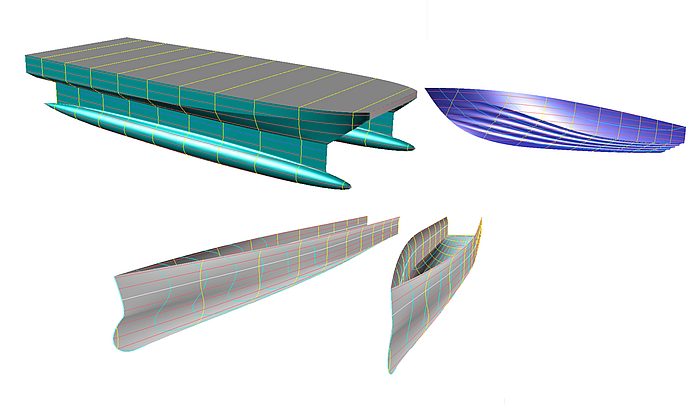
This section is about modeling the geometry of a catamaran hull. Starting point was a paper on the effect of hull shape on performance of high-speed ferries. It is not intended to create a matching copy of a specific hull form, the subject is how to create the characteristic shape features of the design in question. This is attempted using the example of the model s8-z.ms2.
When in the following reference is made to “hull”, not the hull of the complete catamaran is meant, but the immersed body of a ship half (semi hull).
1.1 Shape features
What are the geometric shape features of the design?
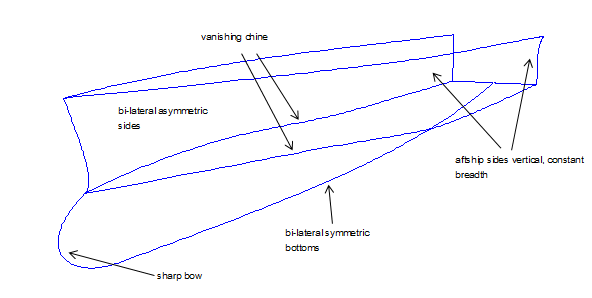
• There is a longitudinal chine, vanishing towards the bow. This chine devides the hull into side and bottom
surfaces.
• In the aftship, the hull sides are vertical and constant in width.
• The outer and inner surfaces of the hull bottom are symmetrical to the center of the hull.
• Outer and inner surfaces of the hull sides are unsymmetrical to the center of the hull.
• Bulbous bow with sharp waterlines
The essential characteristic of the hull shape is the vanishing chine. Tutorial 3, Round Bilge Hull With Vanishing Chine deals with this topic and describes the basic procedure to create such a geometry.
In addition in the present case, the run of the chine in the aftship is straight and parallel to the centerplane.
Because of the asymmetry, two surfaces must be created for the hull sides. Due to the symmetry the inner bottom surface can be a Mirrored Surface of the outer bottom surface.
Notes on the model file
Model Settings (Tools/ Options/...)
.../ Model Units: Meters / Kilograms
.../ Performance: Decimal places = 4; Division multiplier = 2
.../ Dragging: Nudge amount = 0.01 [m]
Coordinate system
Instead of the global coordinate system, the 3-point Frame frame1 is used as coordinate system for the model. This allows to easily move the semi hull to the desired width position.
Hull centerplane
The centerplane of the hull is defined by the 2-point Plane plane1.
Foreshortened representation
Due to the particularly slim shape of the hull inaccuracies in fairness are not easy to spot. At design stage, the model is scaled in X direction by a factor of 0.5, excluding the cps of the bow master curves.
1.2 Hull outside surfaces
Let us first deal with the outer surfaces of the hull (semi hull).
Two longitudinal surfaces are created, the C-spline Lofted Surface side_out for the side and the C-spline Lofted Surface bottom_out for the bottom. Along their common longitudinal edge side and bottom meet in the foreship tangent in transverse direction, but show a break in the aftship. Both surfaces are supported by B-spline master curves.
(See also Tutorials 1 and 2, which discuss the benefits of the C-spline Lofted Surface with B-spline master curves and also describes the vertex curve method.)
We will start with creating the outline of both surfaces, i.e. top edge, rear edge, lower edge, front edge.
Top edge of side
Y-view: the run from bow to stern is horizontal. This is an assumption. The side surface will certainly continue upwards, the mcs are correspondingly upwards to extend. But that does not change the procedure as such.
Z-view: constant width in the aftship
Since a C-spline Lofted Surface will be used, that is, its lofting curves are C-spline Curves, number and position of the cps have to make sure that the curve does not oscillate.
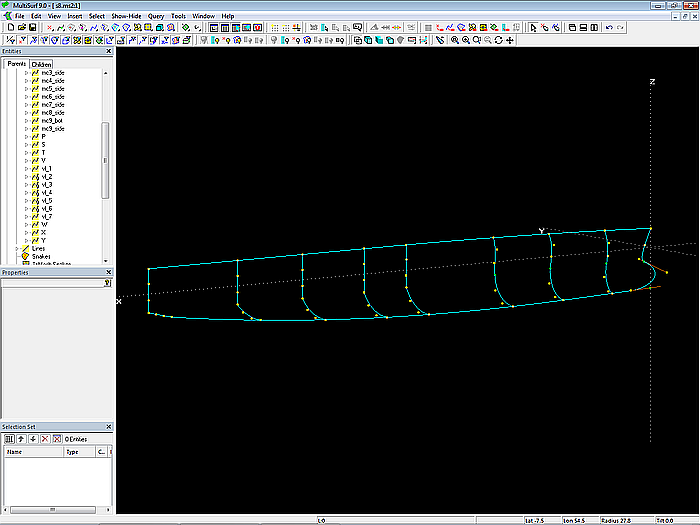
9 cps are used, all defined in the 3-point Frame frame1. The C-spline Curve vl_1 (vertex curve, guide curve for fairing) passes through this points on the top edge of the side surface. The property “Dragging” of these cps is set to Y-direction.
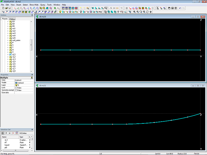
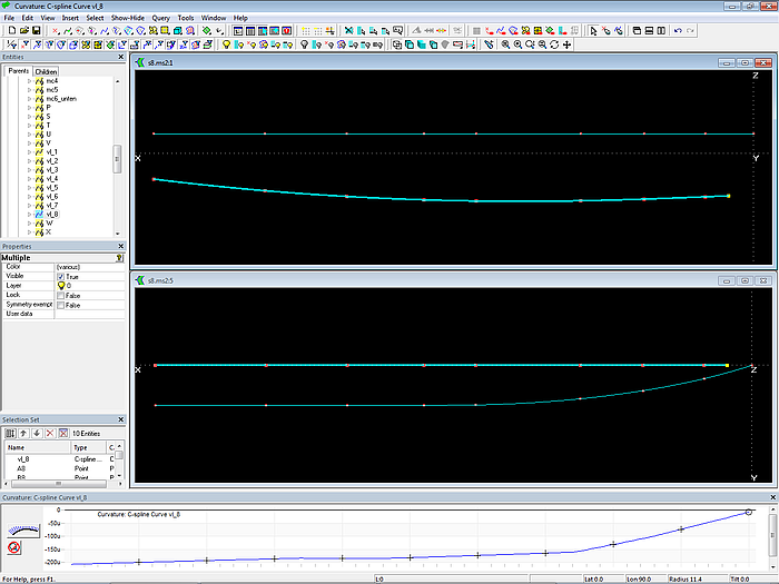
Model s8-z.ms2 – vertex curve vl_1 defines the top edge of the side.
Via View/ Display/ Profile/ Curvature (or the corresponding toolbar button) one can check that the curve runs into a straight line.
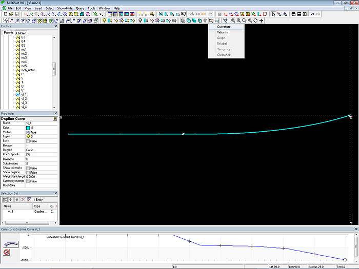
Model s8-z.ms2 – vertex curve vl_1: check of curvature distribution via Profile/ Curvature
Lower edge of bottom
Likewise the vertex curve vl_7 is created for the run of the bottom surface lower edge. For all cps: dy = 0. “Dragging” property set to Z-direction.
Model s8-z.ms2 – lower edge of bottom (vertex curve vl_7)
Forward edge of side and bottom
B-spline Curve mc1_side and B-spline Curve mc1_bot – both run in the midship plane of the hull. All cps: dy = 0. "Dragging" property set to X- and Z-direction.
The number of cps for the mcs of both surfaces is 4, what is no dogma. Use as many as it takes to create the desired shape of the mcs. Property "Degree" of the B-spline Curves is equal to 3. Bead e11, the end point of mc1_side, is also starting point of mc1_bot.
Both curves are connected tangentially.
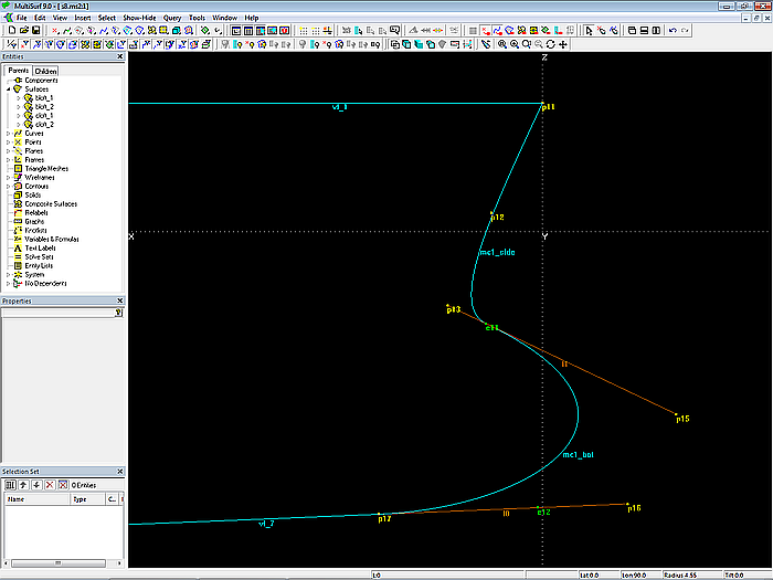
Model s8-z.ms2 – construction of mc1_side and mc1_bot. The tangential link is permanent. Likewise the tangential run of mc1_bot into the bottom contour.
Also note that the last but one cp (Bead e12) of mc1_bot is on the tangent (Line l0) at the starting point of vertex curve vl_7. Thus the smooth entry of mc1_bot into the bottom contour is permanent.
Trailing edge of side and bottom
Side vertical: B-spline Curve mc9_side; "Dragging" in Z-direction for inner cps.
Bottom horizontal: B-spline Curve mc9_bot; "Dragging" in Y-direction for inner cps.
Both mcs run in transverse direction; for all cps: dx = 20 (lengths in design stage foreshortened by factor of 0.5).
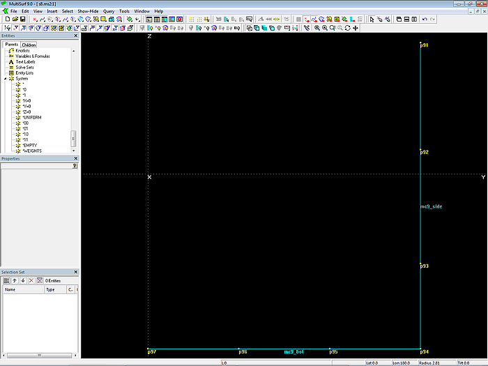
Model s8-z.ms2 – trailing edge mcs: B-spline Curves mc9_side and mc9_bot
So by now most of the curves forming the outline of the hull are determined: top edge of side surface vl_1, lower edge of bottom surface vl_7, as well as leading and trailing edges (mc1_side, mc1_bot, mc9_side, mc9_bot).
From the common longitudinal edge of side and bottom only start and end are specified, namely Bead e11 (bow) and Point p94 (stern).
Inner master curves
Mcs must now be generated for the interior of both surfaces, that is 7 B-spline mcs for the side and 7 B-spline mcs for the bottom. The position of this inner mcs as well as their start and end points is already given by the cps of vl_1 and vl_7. The number of cps per mc is 4, “Degree” = 3. Therefore the vertex curve method can be applied to control surface fairness.
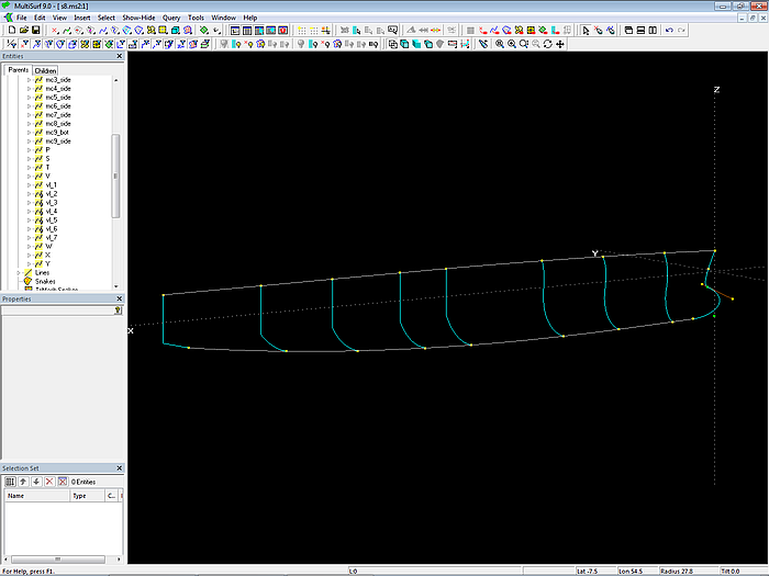
Model s8-z.ms2 – master curves of the hull outside surfaces
The mcs mc6_side to mc8_side run vertically. "Dragging" of cps set to Z-direction.
All internal mcs run in transverse planes; consequently, with a C-spline Lofted Surface the shape of the mc is equal to the shape of the cross-section at the location of the mc.
Property "Dragging" of the cps set to Y and Z. In perspective view a cp can then be moved be moved (dy, dz) without changing its dx.
Model s8-z.ms2 – master curves and control points for side and bottom of the hull outside
To position the cps, the C-spline curves vl_2 to vl_6 (vertex curves) pass through the corresponding cps of the mcs. The common edge of side and bottom surface is described by vl_4.
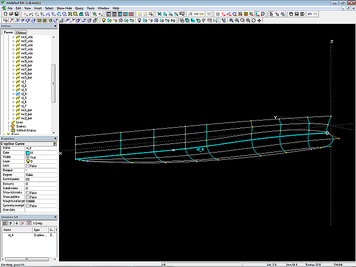
Model s8-z.ms2 – vertex curves for cp positioning; vl_4 defines the run of the chine, vanishing in the foreship.
For the tangential link of mc2, mc3 and mc4 the same construction is used as for the side and bottom bow mcs.

Model s8-z.ms2 – tangential linking of mcs 2, 3 and 4
Surfaces
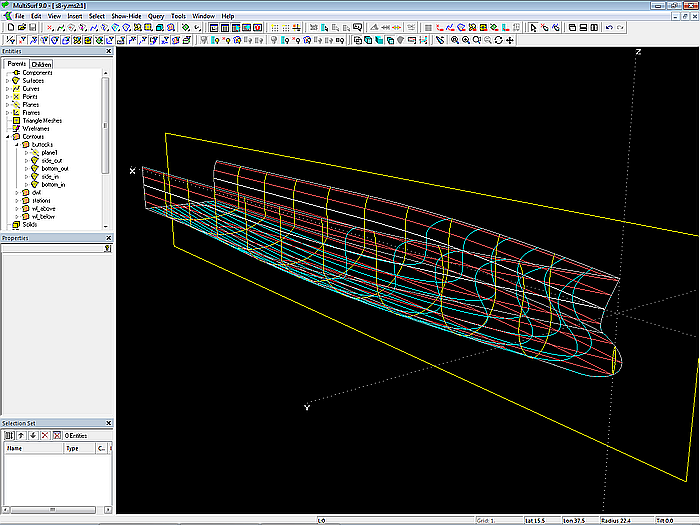
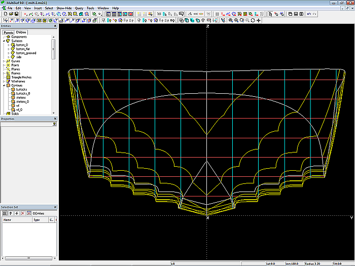
After the definition of the inner mcs, the two C-splines Lofted Surface side_out and bottom_out are generated. Subsequently, Contours entities are created for stations, buttocks and waterlines.
Model s8-z.ms2 – hull outside surfaces (foreshortened length)
So much to the construction for the outer surfaces of the catamaran hull.
1.3 Hull inside surfaces
Bottom
In the present geometry, outer and inner surfaces of the hull bottom are symmetrical to the centerplane. The bottom inner surface can thus be generated by the Mirrored Surface bottom_in.
Side
Outside and inside surfaces of the hull side are not symmetrical to the centerplane. Therefore, the C-spline Lofted Surface side_in is created. Its mcs are B-spline Curves with 4 cps each. Cp3 and cp4 are Mirrored Points of the corresponding cps of the mcs for the outside surface side_out.
Changes to the outer surfaces side_out and bottom_out are thus automatically transfered to the inner surfaces side_in and bottom_in by the use of a Mirrored Surface for the bottom and Mirrored Points for the side.
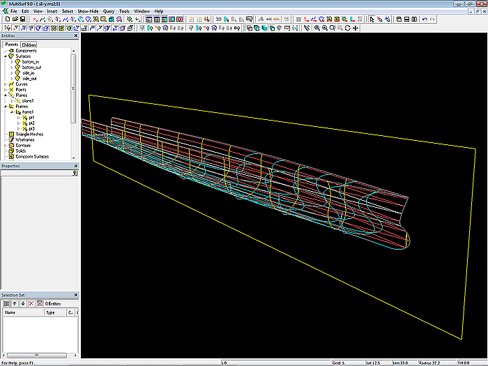
Model s8-z.ms2 – mcs for the side inner suface – cp3 and cp4 are Mirrored Points of the corresponding cps of the mcs for the outer surface of the side.
Model s8-z.ms2 – outer and inner surfaces of the semi hull (length foreshortened)
Note
As mentioned above, during the design stage the model is foreshortened in length. In order to bring the model to its true length, the X coordinates of the cps must be scaled by a factor of 2 (Edit/ Transform/ Scale). However, with the exception of the cps of the bow mcs. To simplify the selection of the points to be scaled there is the Entity List entities_to_scale. Select it in the Entities Manager, then main menu/ Select/ Expand Entity List/ First Generation. This allows the model view to be changed between foreshortened and true length.
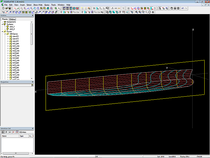
Model s8-z.ms2 – outer and inner surfaces of the semi hull (true length)
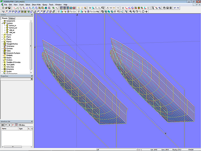
Model s8-z.ms2 – catamaran hull (true length)
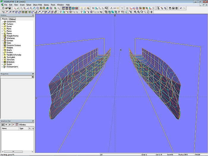
Model s8-z.ms2 – catamaran hull (true length)
2 Multi-concave hull bottom
Subject of this section is the construction of the geometry model for a powerboat with a multi-concave hull bottom. Starting point were some photos of the mould for a boat with a series of longitudinal grooves in the bottom surface. The following discussion is about modeling this shape feature using the model mch-1.ms2 as an example.
First, a typical hard-chine powerboat hull is modeled. Its bottom surface will then be the base for a multi-concave bottom.
2.1 Shape feature
Fast powerboats typically feature sprayrails attached to the hull bottom. In the case in question the bottom surface shows several longitudinal chines, between them the surface is indented (concave). In cross-section these indentations look like a mixture of sprayrail and tunnel.
Notes on the model file
Model Settings (Tools/ Options/...)
.../ Model Units: Meters / Kilograms
.../ Performance: Decimal places = 4; Division multiplier = 2
.../ Dragging: Nudge amount = 0.001 [m]
Coordinate system
The global coordinate system is used.
Hull centerplane
The centerplane of the hull is the XZ-plane of the global coordinate system.
2.2 Hull with standard bottom
The form of a typical hard-chine hull for a powerboat is assumed. It consists of two surfaces, the C-spline Lofted Surface side for the topside and the C-spline Lofted Surface bottom_0 for the bottom surface. Side and bottom are joined along their common longitudinal edge, the cross-sections show a break. Both surfaces are supported by 6 B-spline master curves.
The construction of hard chine hulls for powerboats is covered in detail in Tutorial 4, Chine-Form Powerboat Hulls.
First, the outlines of both surfaces are created, i.e. top edge of side, chine, bottom contour and stem and trailing edge of side and bottom.
Top edge of side, chine, bottom contour
The run of the upper edge of side, the chine and the bottom contour are defined by the C-spline Curves vl_1, vl_3 and vl_5 (vertex curves, guide curves for fairing). Each curve is supported by 6 cps.
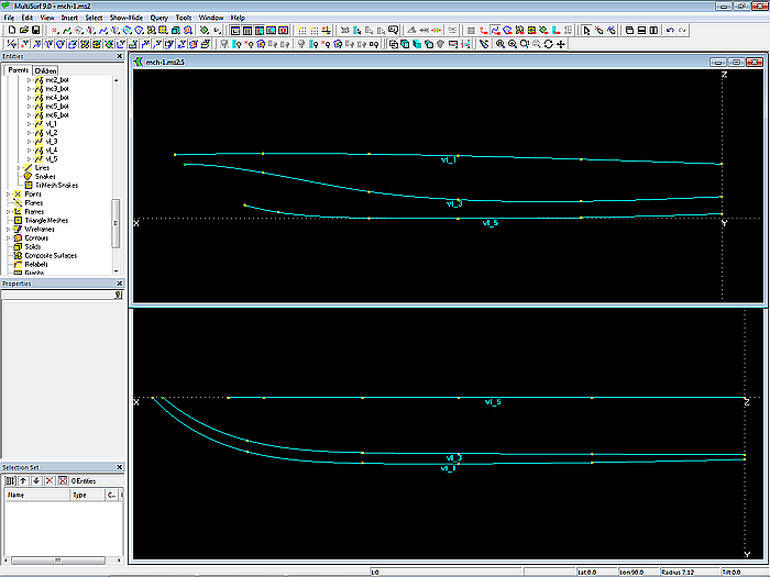
Model mch-1.ms2 – the vertex curves vl_1, vl_3 and vl_5 show the run of the top edge of side,the chine and the bottom contour.
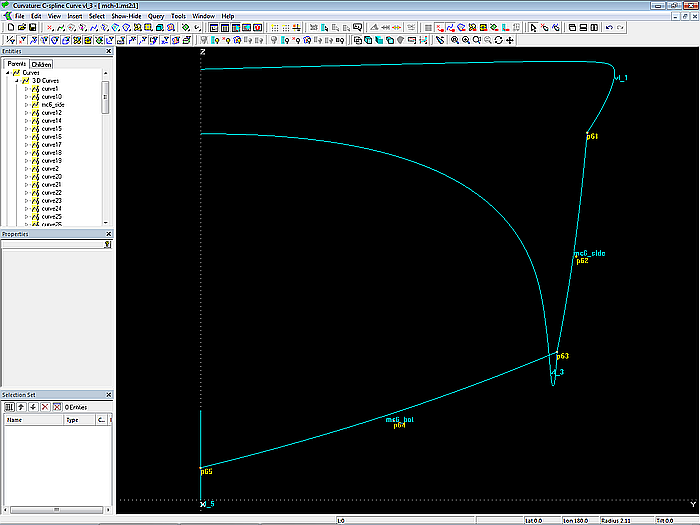
Via View/ Display/ Profile/ Curvature (or the corresponding toolbar button) one can check whether the curvature distribution of these curves is harmonious.
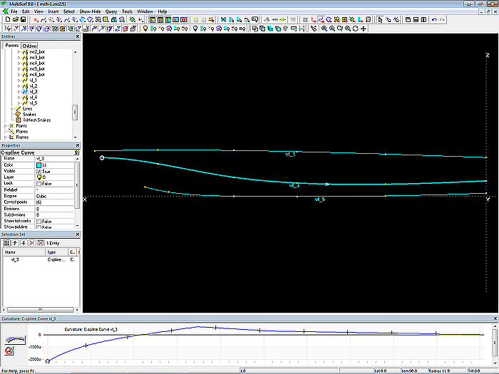
Model mch-1.ms2 – control of curvature distribution of vertex curve vl_3 via Profile/ Curvature
For all cps of the bottom contour (vl_5) the value dy = 0; the property "Dragging" is set to Z-direction.
Stem – leading edges of side and bottom
The shape of the stem curve is defined by the two B-spline Curves mc1_side and mc1_bot, each supported by 3 cps. Property “Degree” is equal to 2.
The last but one cp (Bead e14) of mc1_bot lies on the tangent (Line l0) at the start of the bottom contour (vl_5). Due to this construction, the leading edge of the bottom surface runs smoothly into the bottom contour.
The two curves mc1_side and mc1_bot are also connected tangentially. To do this, first Line l1 is spanned between Point p11 (stem head) and Bead e14 on Line l0. Bead e13 is then on l1 as end point of mc1_side and start point of mc1_bot.
Since its inner cp also lies on Line l1, the B-spline Curve mc1_side is straight.
Thus free points are only Point p11 and Point p15, both defined with dy = 0. "Dragging" property set to X- and Z-direction.
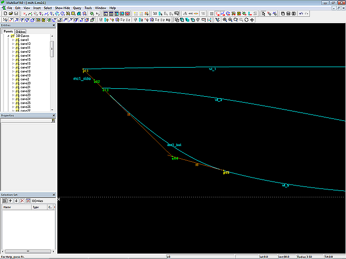
Model mch-1.ms2 – construction of the bow mcs mc1_side and mc1_bot. Tangential link is hardwired, as is the smooth entry of mc1_bot into the bottom contour.
Trailing edges of side and bottom
The aft end of side and bottom surfaces are determined by the B-spline Curves mc6_side and mc6_bot. Both mcs run in a transverse plane.
Model mch-1.ms2 – master curves at the aft end of the hull are the B-spline Curves mc6_side and mc6_bot.
So by now the top edge of the side surface (vl_1), the lower edge of the bottom surface (vl_5), the chine (vl_3) as well as the leading and trailing edges (mc1_side, mc1_bot, mc6_side, mc6_bot) of the hull have been created.
Inner master curves
Now the mcs for the interior of both surfaces must be defined, i.e. 4 B-spline mcs for the side and 4 B-spline mcs for the bottom. The number of cps per mc is 3, “Degree” = 2. The X-position of the inner mcs and their start and end points are already given by the cps of vl_1, vl_3 and vl_5. Only one further cp must be created in between.
Since all mcs are of the same curve type, each with the same number of cps, the vertex curve method can be applied to create fair surfaces. Accordingly, the two C-spline Curves vl_2 and vl_4 are defined, supported by the inner cps of the mcs for side and bottom.
Model mch-1.ms2 – master curves, control points and vertex curves of the hull surfaces
Except for the stem mcs (mc1_side, mc1_bot) and mc2_bot, all mcs run in transverse planes. "Dragging" of their cps is set to Y- and Z-direction. So iIn perspective view they can then be moved (dy, dz) without changes to dx.
Hull surfaces
After definition of the inner mcs, the two C-spline Lofted Surface side and bottom_0 are generated. Subsequently, Contours entities are created for stations, buttocks and waterlines.
Model mch-1.ms2 – hull base surfaces
So much for the construction of the model for the base surfaces of the powerboat hull.
2.3 Hull with multi-concave bottom
Master curves – rule-based approach
In the present geometry problem, the bottom should not be smooth, but have grooves, indentations, running fore to aft. Merely a strip aside the bottom contour is part of the previously defined bottom surface.
Based on the existing bottom mcs, new mcs are created with indentations. With these mcs the multi-concave bottom is created as a C-spline Lofted Surface. Its shape is not freely defined, i.e. by curves formed by freely movable points. On the contrary, with the help of variables and formulas as well as certain rules, geometrically similar curve segments are created and then combined with a PolyCurve to form the new mcs.
The following assumptions are made:
• Number of grooves: 4
• Curve segments: B-spline Curve, 5 cps, “Degree” = 2
- start and end on mc for the base bottom surface
- equal arc lengths between start and end
- start horizontal with straight part
- vertical tangent at end
The boundary between multi-concave bottom and smooth bottom is defined by the C-spline Curve vl_groove_4. It passes through the Beads e14, e24, e34, e44, e54 and e64 on mc1 to mc6 of the base bottom surface bottom_0.
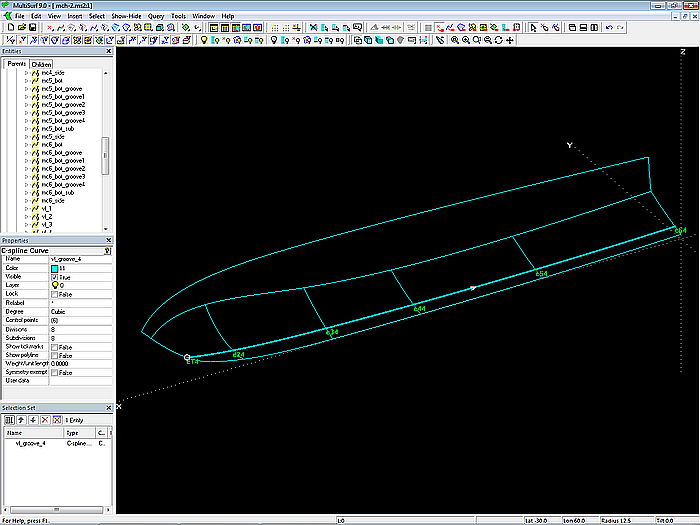
Model mch-1.ms2 – dividing curve between multi-concave and smooth bottom
The construction of the new mcs with indentations is to be described using mc5 as an example.
First, on mc5_bot the arc length from its beginning (t = 0) to the Bead e54 is determined and divided by the number of grooves. This value is calculated using the Formula l_mc5_bot_groove. With this arc length as distance from each other, the three Arc-length Beads e51, e52 and e53 are now created on mc5_bot.
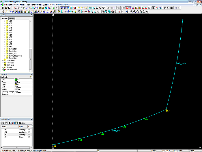
Model mch-1.ms2 – master curve mc5_bot with 4 equally spaced beads
If e54 is moved, the position of the other beads changes automatically; the geometric relation (division into 4 parts of equal arc-length) is retained.
Point g5_11 is now determined with Point p53 as reference point; coordinates dx = 0 and dz = 0. Its distance dy is calculated using the Formula d51:
d51 = c2 * l_mc5_bot_groove
The Variable c2 is set to the value -0.145. That is, Point g5_11 is offset 14.5% of the groove width inboard relative to Point p53.
Point g5_12 is defined in a similar way. The Formula d52 determines the horizontal distance dy from p53:
d52 = c3 * l_mc5_bot_groove
The Variable c3 is set to the value -0.65. Point g5_12 is thus offset 65% of the groove width inwards relative to Point p53.
Similarly, Point g5_13 is generated, now with the Formula d53:
d53 = c4 * l_mc5_bot_groove
The Variable c4 is set to the value 0.21. Bead e51 is reference point of Point g5_13, and it is offset horizontally by dz = d53.
The B-spline Curve mc5_bot_groove1 is now determined with points p52, g5_11, g5_12, g5_13 and e51 (Degree = 2).
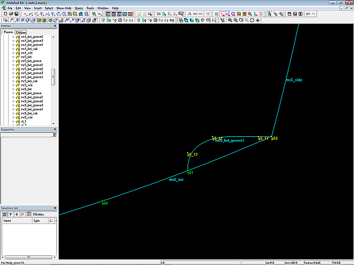
Model mch-1.ms2 – cross-section of groove 1 at mc5
Like the underside of a spray rail, mc5_bot_groove1 runs halfway between g5_11 and g5_12 straight and horizontal.
The remaining grooves on mc5 are generated in an analogous manner.
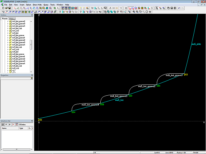
Model mch-1.ms2 – B-spline Curves describe the cross-section shape of the grooves.
All 4 cross-sections are now combined into the PolyCurve mc5_bot_groove.
The construction described is then repeated for mcs 3, 4 and 6. The property “Specify end t-values” of the PolyCurves is set to “Yes”.
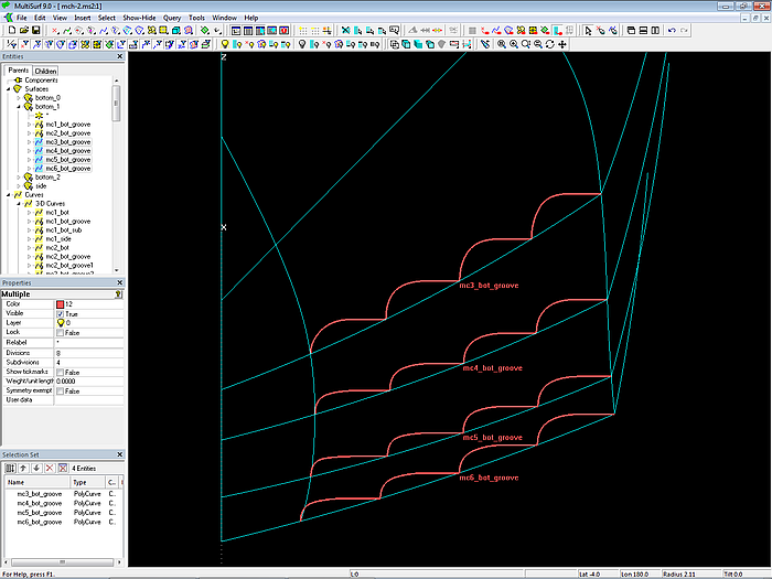
Model mch-1.ms2 – mcs (PolyCurves) for the multi-concave bottom surface
The indentations at mc2 look a little different. Here, an Arc entity of Type = 3 is used as cross-section shape. The camber refers to the midpoint of the chord of the arc. It is defined by the Formula d2:
d2 = c1 * l_mc2_bot
The Variable c1 is set to the value 0.2.
Model mch-1.ms2 – Arcs are used on mc2 for the groove cross-sections.
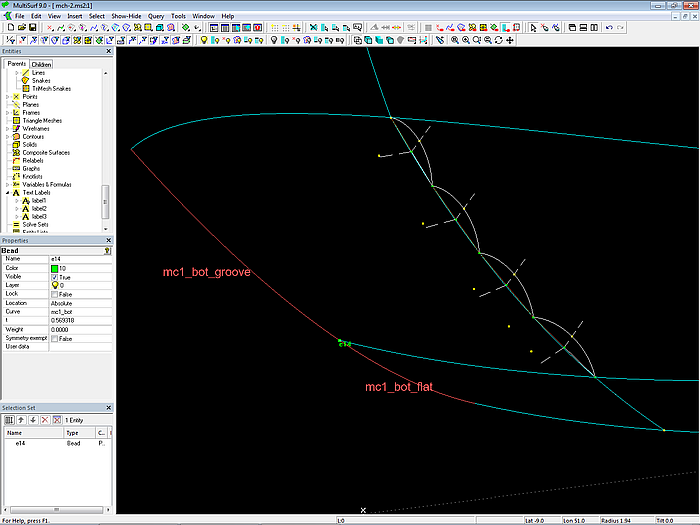
For the bow-mc of the multi-concave bottom the SubCurve mc1_bot_groove is used. This is the part of mc1_bot from start (t = 0) to Bead e14.
With all the new mcs for the multi-concave bottom available now, the C-spline Lofted Surface bottom_grooved is created.
For the part of the hull bottom from the edge of the multi-concave bottom to the bottom contour the C-spline Lofted Surface bottom_flat is generated. Its supports are SubCurves, defined with the Beads e14 to e64 on their host mcs for the curve part from bead position until t = 1.
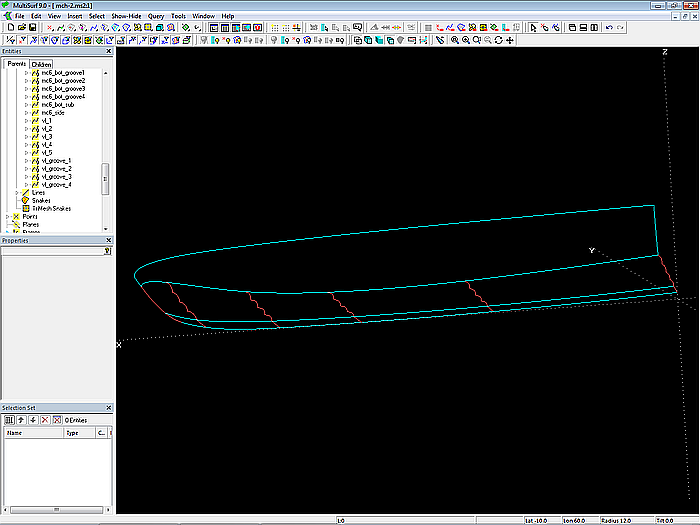
Model mch-1.ms2 – mcs for multi-concave and smooth bottom parts
Model mch-1.ms2 – multi-concave and smooth bottom (C-spline Lofted Surfaces bottom_grooved and bottom_flat)
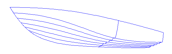
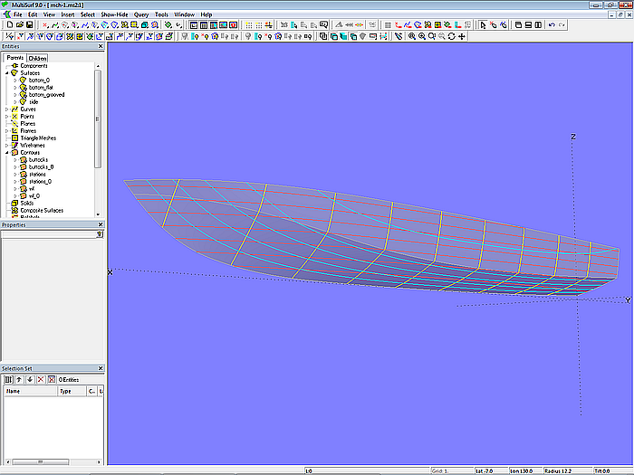
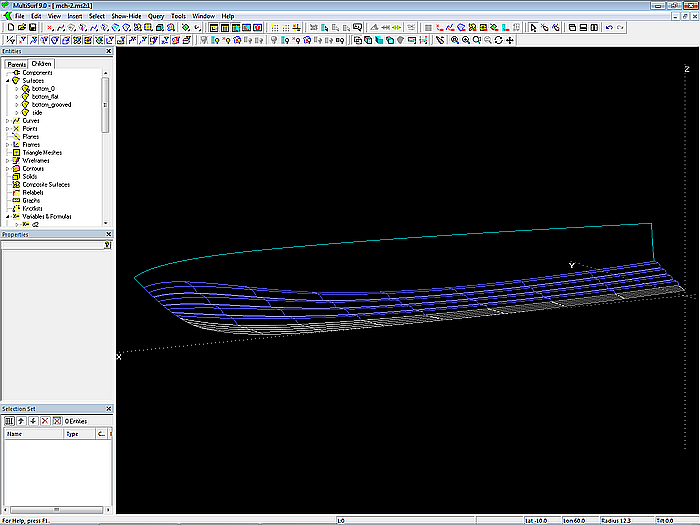
Model mch-1.ms2 – powerboat hull with multi-concave bottom
Model mch-1.ms2 – powerboat hull with multi-concave bottom
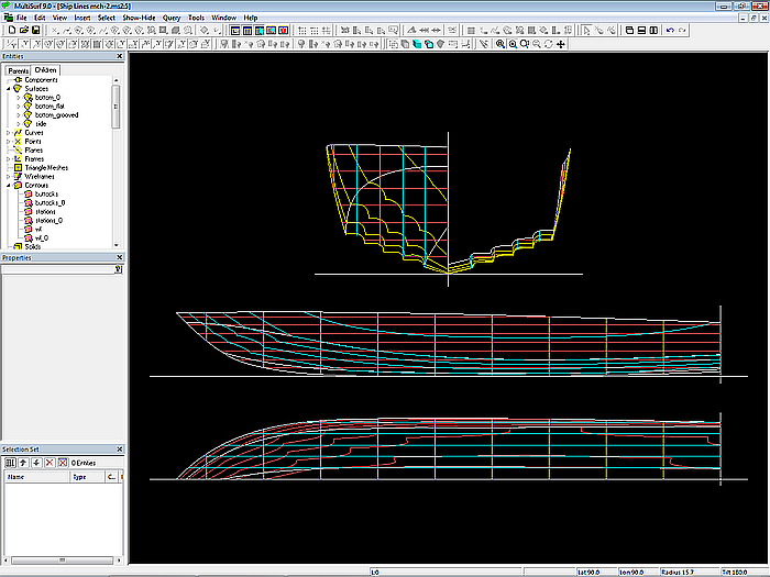
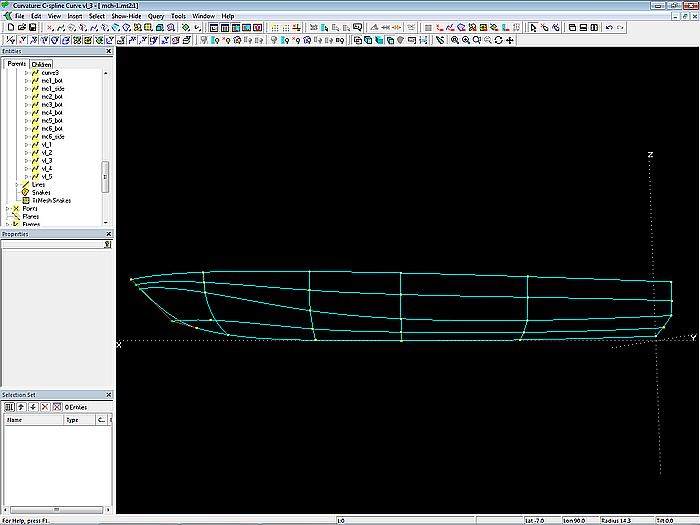
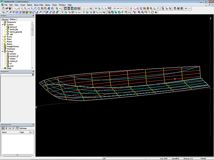
Model mch-1.ms2 – powerboat hull with multi-concave bottom (Ship Lines view)
In the presented model mch-1.ms2, the mcs for the multi-concave bottom are generated using Variables and Formulas according to specific rules based on the mcs of the standard smooth bottom. The cross-section shape of the grooves is geometrically similar. By changing the values of the Variables c1, c2, c3 and c4 the shape can be modified. When editing the basic hull form or the boundary between grooved and smooth bottom part, the grooves will change automatically, but retain their form characteristics (curve starts horizontally, straight portion, curve ends vertically).
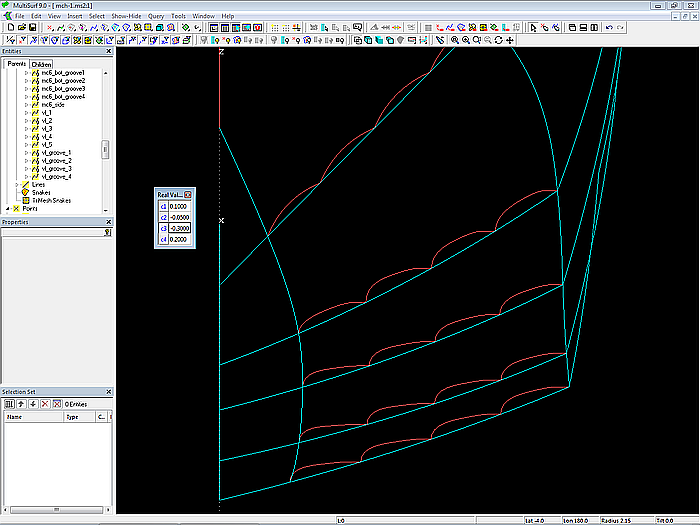
Model mch-1.ms2 – the shape of the mcs for the multi-concave bottom can be modified by a few variables.
In model mch-1.ms2 it is assumed that the value of the Variables c1 to c4 does not change with length, that is, they are the same for all mcs. With appropriate formulas, a length dependency can be added to the model. So that, for example, the length of the straight portion of the groove increases towards the stern.
Other geometrically similar cross-sectional shapes can be achieved using other rules.
Master curves – free-form approach
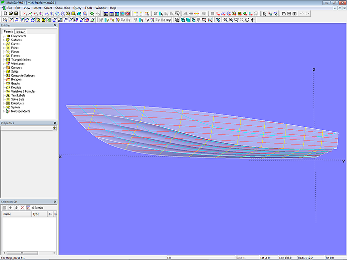
One can also take a free-form approach. This is described in model mch-freeform.ms2. Side and base surface of the bottom are the same as in model mch-1.ms2.
The indentations are B-spline Curves, also those on mc2. The cps are free points, they do not have any reference to variables and formulas. By manually moving the cps, the cross-sectional shape of the multi-concave bottom can be adapted to the design ideas.
In order to achieve fairness of the grooves, corresponding cps are connected by C-spline Curves. If these curves run evenly and smoothly, the grooves are also fair.
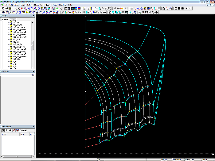
Model mch-freeform.ms2 – master curves and vertex curves of the multi-concave bottom surface; free-form approach
Are there precise ideas about the cross-sectional shape of the individual grooves and can these not be achieved by geometric rules, the free-form approach is preferable. Then there are no design restrictions. However, positioning a considerable amount of free points while achieving fairness will take its time and must be repeated whenever the basic hull geometry is modified.
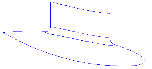
Model mch-freeform.ms2
3 Swath ship: pod-strut transition
The design exercise described in this section is about the construction of a transitional surface between two adjoining surfaces. First, two general solutions are presented. Then an application is shown using the example of a Swath ship.
When two surfaces meet, a gradual transition between them may be desired for various reasons. In Tutorial 18, Form Features – about particularities of geometry of hull, deck and keel it is shown in the section “Roundings” by means of several examples how to model appropriate fillets. In the present case, the transition between strut and submarine hull as in a Swath ship will be discussed.
3.1 Shape features
Geometric features of the transition surface:
• tangential entry into both surfaces
• shape is variable
3.2 Base model
The model base.ms2 is basis for the further discussion. It contains the two surfaces pod_0 and strut_0. For reasons of clarity, pod_0 is only a part of the submerged body.
Surface pod_0 is a B-spline Lofted Surface supported by 6 mcs. Where mc1 is given by Point mc1_pod, and mc6 by Point mc6_pod; both mcs are not curves of finite length, but to one point degenerated curves. The inner mcs are B-spline Curves with 5 cps each and Degree = 3.
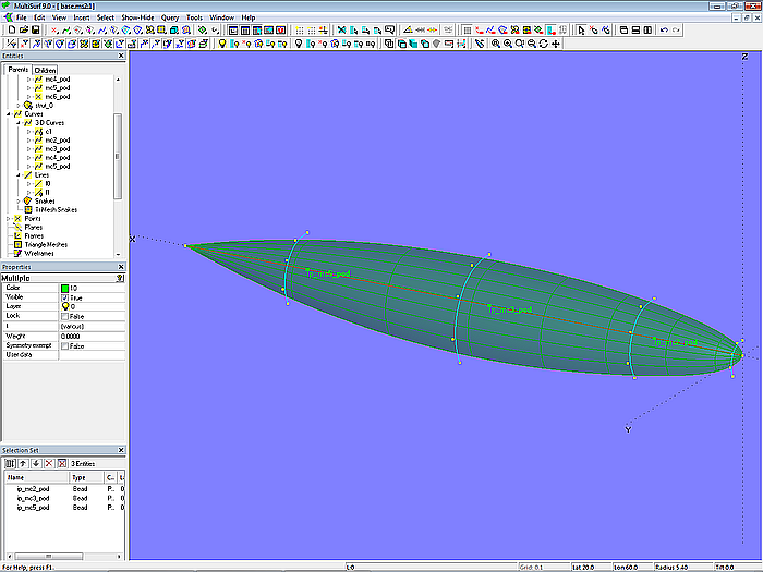
Model base.ms2 – B-spline Lofted Surface pod_0
The cps of the inner mcs are relative points to beads on Line l0, the connecting line between Point mc1_pod and Point mc6_pod. By this relationship, the longitudinal shape can be changed by moving the beads.
Basis for the strut is the C-spline Curve c1, determined with 4 cps; it describes the waterline shape. Curve c1 is projected onto pod_0 as Projected Snake sn1. Between c1 and sn1 the Ruled Surface strut_0 is spanned. Its leading edge is not round like those of a keel or rudder, but sharp.
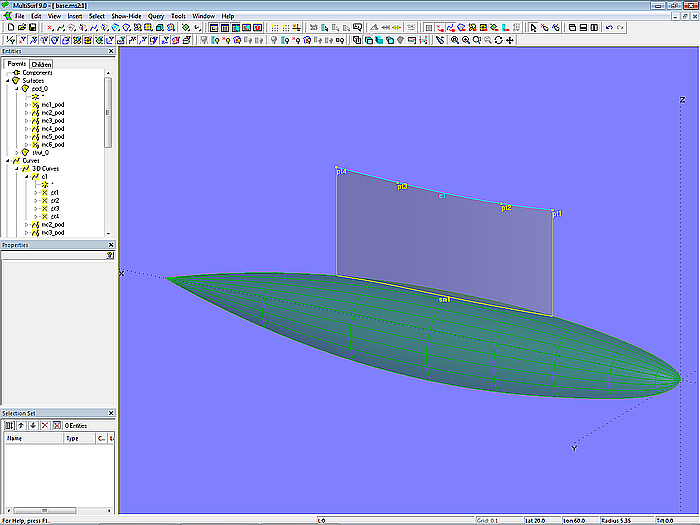
Model base.ms2 – Ruled Surface strut_0
3.3 Rounding 1 – Rolling Ball Fillet
The Rolling Ball surface type offers a rounding method for two adjoining surfaces. It is the adjacent portion of the envelope of a ball (sphere) rolling between the two surfaces. This is shown in the model base_rolling_ball.ms2.
Parents of a Rolling Ball Fillet are the curve along which the ball should roll, the two surfaces to fillet and the ball radius. Accordingly, in the model base_rolling_ball.ms2 the Rolling Ball Fillet fillet_0 is defined with the Projected Snake sn1 and the surfaces strut_0 and pod_0. The radius is set to 0.15 m.
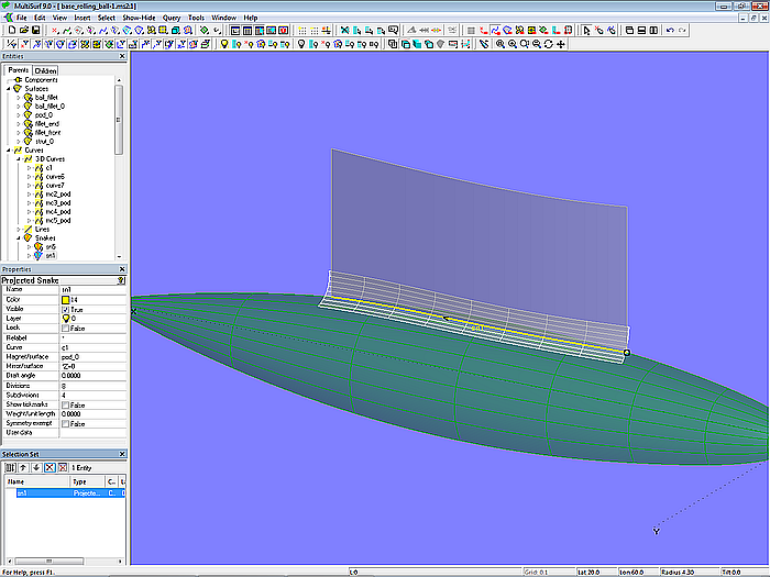
Model base_rolling_ball.ms2 – Rolling Ball Fillet as rounding
Due to the shape of the strut the rounding fillet_0 is open at both leading edge and trailing edge. It is closed with the two Tangent Boundary Surfaces fillet_front and fillet_end. Their construction will be explained using the surface fillet_front.
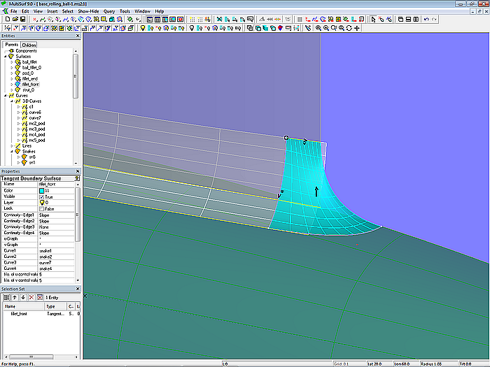
Model base_rolling_ball.ms2 – Tangent Boundary Surface fillet_front
The fillet piece must be tangent along three edges to the adjacent face, i.e. tangent to pod_0, to fillet_0 and to strut_0. This means that each of these edges is a Snake on the corresponding surface.
Let us start with snake sn1_front, a Line Snake on the surface fillet_0 between Ring r1 on the top edge of fillet_0 (Edge Snake ue_fillet_0) and Ring r2 on its bottom edge (Edge Snake bt_fillet_0). So Line Snake sn1_front determines the size of the end piece in longitudinal direction.
Snake sn2_front is a B-spline Snake on pod_0 defined with Copy Ring r3 on Projected Snake sn2, Tangent Magnet m1 and Ring r4 on the top edge of pod_0 (Edge Snake ue_pod_0). By using the entity Tangent Magnet, the relationship is firmly established that the bottom edges of fillet_front (end piece) and fillet_0 (Rolling Ball Fillet) are tangent to each other.
Snake sn3_front is Projected Snake of the portion of the top of fillet_0 from its forward end up to Ring r1 (SubSnake sn3).
Finally, as last parent of the Tangent Boundary Surface fillet_front its front edge is created by the B-spline Curve c_front.
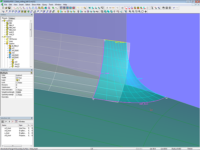
Model base_rolling_ball.ms2 – Tangent Boundary Surface fillet_front
The end piece of the fillet aft is constructed in the same way.
Finally, the surface parts of strut and submerged body, not covered by the fillet, are created (Trimmed Surface strut and Trimmed Surface pod). The portion of the fillet between the end pieces is defined by SubSurface fillet.
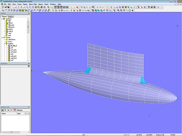
Model base_rolling_ball.ms2 – rounding between strut and buoyancy body with Rolling Ball Fillet (radius constant)
On closer inspection, however, it is noticeable that buttocks through the fillet do not run fair.
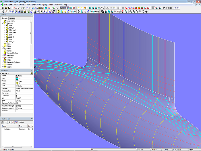
Model base_rolling_ball.ms2 – unfairness of buttocks (Rolling Ball Fillet with constant radius)
This can be corrected if the radius of the rounding changes over the length. For this purpose the surface type Rolling Ball Fillet offers the property "Graph". When a Rolling Ball Fillet entity is inserted into a model, the system object “*” is entered as default. This means, that the radius should remain constant over the length of the fillet surface. Should the radius change, a Graph entity must be used for the "Graph" property. In model base_rolling_ball.ms2 there is already the B-spline Graph graph1 for this. Will now graph1 instead of "*" be used, the ball radius is variable.
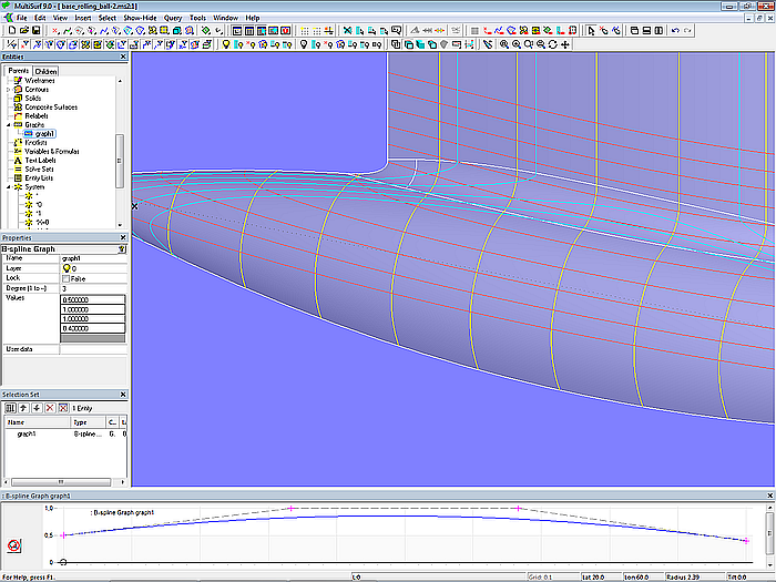
Model base_rolling_ball.ms2 – Rolling Ball Fillet with B-spline Graph graph1; the fillet radius varies over length.
3.4 Rounding 2 – Blend Surface
In model base_blend_surface.ms2 an entity of the Blend Surface type is used for the rounding.
A Blend Surface requires four snake supports: two snakes on surface 1 (strut_0) and two snakes on surface 2 (pod_0). Line Snake sn2 on strut_0 sets the start of the fillet. The other snake on surface 1 is its bottom edge (Edge Snake bt_strut_0). Projected Snake sn1 is the one snake on surface 2, the other is the B-spline Snake sn4 created with 5 control magnets. It defines the end of the rounding on pod_0. With these 4 snakes the Blend Surface fillet is determined.
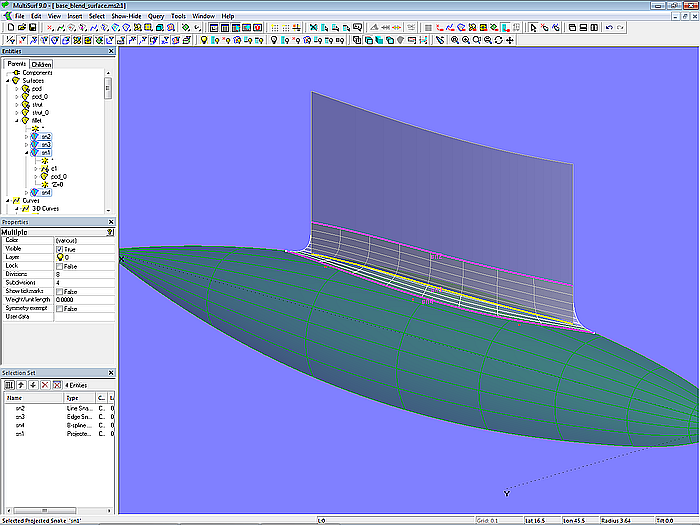
Model base_blend_surface.ms2 – fillet with Blend Surface
With the "Type" property of the Blend Surface, the shape of the rounding in transverse direction can be modified. For Type = 1 the join to the two surfaces is tangential, for Type = 2 it is both tangential and continuous in curvature; the fillet is narrower.
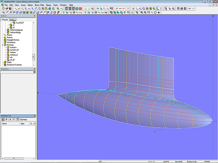
Model base_blend_surface.ms2 – fillet with Blend Surface
3.5 Application – Swath ship
After this preliminary explanations on roundings, we will now turn to the actual design task: the construction of a gradual transition between struts and submarine buoyancy bodies (pods) of a Swath ship. This is to be shown using the model swath-1.ms2 as an example.
Swath (small waterplane area twin hull) means a catamaran vessel with small waterline area. The buoyancy of a Swath ship is provided by two submarine hulls connected to the above water hull with deck platform by narrow webs or struts from each of the streamlined submarine buoyancy bodies.
Notes on the model file
Model Settings (Tools/ Options/...)
.../ Model Units: Meters / Kilograms
.../ Performance: Decimal places = 4; Division multiplier = 2
.../ Dragging: Nudge amount = 0.01 [m]
Coordinate system
Instead of the global coordinate system, the 3-point Frame frame1 is used as coordinate system for the semi hull. This allows to move the hull easy to the desired width position.
Semi hull centerplane
The centerplane of the semi hull is defined by the 2-point Plane plane1.
Model construction
The model geometry can be divided into outside and inside hull (semi hull), deck platform, the fully submerged buoyancy body and the strut between the underside of the hull and the buoyancy body, which breaks the sea surface.
Hull surfaces
The outer and inner surfaces of the hull and the platform are formed by Ruled Surfaces, which meet along common longitudinal edges with a break (hull in hard-chine form). They are supported by B-spline master curves with 5 and 6 control points, respectively.
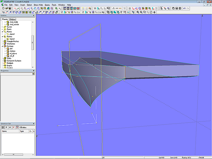
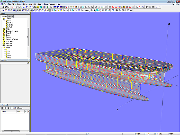
Model swath-1.ms2 – master curves of the surfaces for semi hull and platform
Buoyancy body and strut
In contrast to the introductory examples above, the buoyancy body is created by a Revolution Surface (hull_pod_0). Its meridian is the B-spline Curve c1; angle of rotation = 360°).
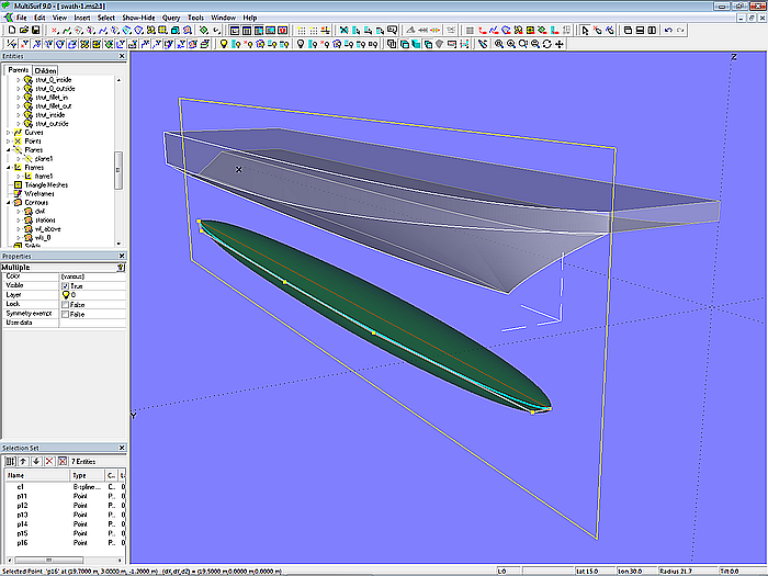
Model swath-1.ms2 – the fully submerged buoyancy body is a Revolution Surface.
The outer surface of the support between buoyancy body and hull is also a Ruled Surface (strut_0_outside), spanned between B-spline Curve c2 and its projection onto the Revolution Surface hull_pod_0 (Projected Snake sn1_out).
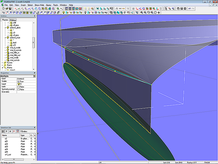
Modell swath-1.ms2 – support between buoyancy body and semi hull by Ruled Surface
For the inside surface of the strut (strut_0_inside) a Mirrored Surface is used. By this relationship changes to the shape of the outside are automatically transferred to the inside.
Transition pod – strut
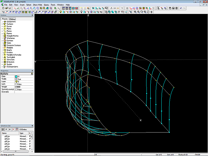
A Blend Surface is chosen as the surface for the transition between buoyancy body and strut. For its definition 4 snakes are required. Snake 1 on the strut is Line Snake sn2_out between Ring r1 (on leading edge of strut) and Ring r2 (on trailing edge of strut). It determines the start of the fillet. Snake 2 on the strut is its bottom edge (Edge Snake sn3_out). Snake 3 is on the buoyancy body as Projected Snake sn1_out. Snake 4 defines the end of the fillet on the pod; this is B-spline Snake sn4_out supported by 5 cps.
With these 4 snakes the Blend Surface strut_fillet_out is then created. The fillet on the strut inside is defined by the Mirrored Surface strut_fillet_in.
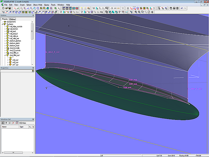
Model swath-1.ms2 – Blend Surface as fillet between strut and buoyancy body
Finally, the surface parts of strut and pod, that are not covered by the fillets, are created (Trimmed Surfaces strut_outside, strut_inside and hull_pod).
Model swath-1.ms2 – Shaded view
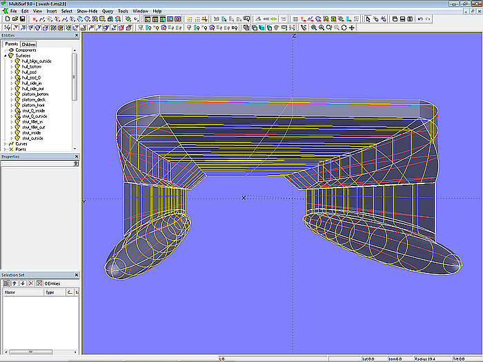
Model swath-1.ms2 – Shaded view
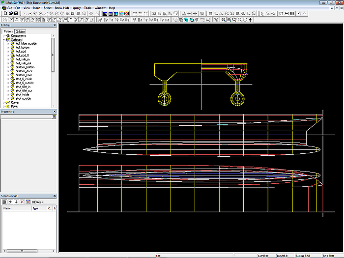
Model swath-1.ms2 – Ship Lines view
======================================================================================