Round Bilge Hull With Vanishing Chine
A complex variation of the round bilge hull theme
by Reinhard Siegel
Introduction
Modern racing yachts feature a single longitudinal chine. On some boats the chine runs full length from stem to stern, on others it starts at the stern, but vanishes somewhere forward of the middle of the hull.
In this article I would like to explain on the basis of the model sy15_vanish_chine.ms2 how to create in MultiSurf a round bilge hull with a partial length chine, which proceeds from the stern. This is not about making a hull with specific dimensions, but shows which method is practical, so in the end you achieve what you imagine.
Abbreviations used:
cp: control point (support point)
mc: master curve = support curve
cp1, cp2, ...: denotes 1st, 2nd, ... point in the list of supports of a curve. It is not an actual entity name.
mc1, mc2, ...: denotes 1st, 2nd, ... curve in the list of supports of a surface. It is not an actual entity name.
In the following the terms used for point, curve and surface types are those of MultiSurf. This may serve the understanding and traceability.
The hull is derived from the models sy15.ms2 and sy15_full_chine.ms2, which are discussed in the articles „On the Modeling of Round Bilge Hulls“ and „Round Bilge Hull With Full Length Chine“.
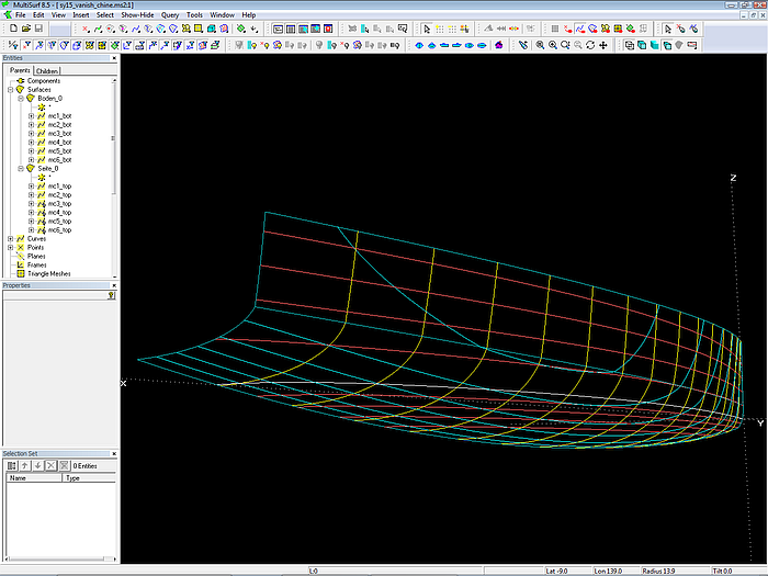
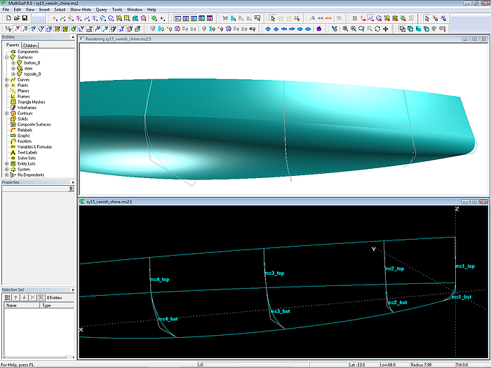
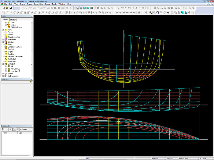
Model sy15_vanish_chine.ms2 opened in MultiSurf.
Concept
The hull is composed of 2 surfaces, topside and bottom. Their modeling is analogous to the modeling of a standard round bilge hull.
Topside and bottom are created as C-spline Lofted Surfaces, each one supported by 6 mcs, all B-spline Curves. The bottom mcs are supported by 4 cps, the degree is 3. The topside mcs have 3 cps, degree is 2.
The first cp of a bottom mc serves also as 3rd cp of the corresponding topside mc, so the mcs are linked together. Mcs 4, 5 and 6 of topside and bottom are joint with a break. The forward 3 mcs join tangent.
Why vertex curves?
Vertex curves are guiding curves for fairing a C-spline Lofted Surface. A vertex curve is a C-spline Curve which connects corresponding cps. If vertex curves run in a harmonious, regular fashion, the surface is fair.
The Vertex Curve Method requires, that mcs are of the same kind (B-spline Curve) and each mc has the same number of cps.
Vertex Curve vl3 forms the chine. Although it runs from stem to stern, there will be no chine where the mcs of topside and bottom join with no break.
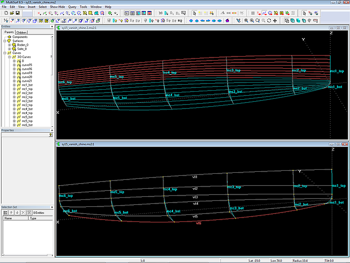
The C-spline Lofted Surfaces topside_0 und bottom_0 are each supported by 6 mcs. Vertex Curves pass through corresponding cps.
How to link two B-spline Curves smoothly?
The forward 3 mcs must be connected fairly. To join two B-spline Curves with no break we use their tangency property. A B-spline Curve always starts tangent to the first segment and always ends tangent to the last segment of the polyline through its cps. Thus, if two B-spline Curves join, and the neigbours to the common point are in line, the transition is tangent.
This required relationship for the forward 3 mcs is hardwired by a simple construction: a) a line is spanned between the first two cps of the bottom mc, b) a bead on this line is the second but last cp of the topside mc.
For example, mc3_top and mc3_bot: the Line line_3 between Point p33 and Point p34 is host of the Bead p32_e. All three points keep automatically aligned when edited, thus there is no break between both mcs.
All cp2 of the 3 forward topside mcs are beads; one can slide them up and down on their lines. Their movement is thus limited, but this limitation assures a smooth joint. While the cp2 of the 3 aft topside mcs are Point entities and as such can be moved freely in space.
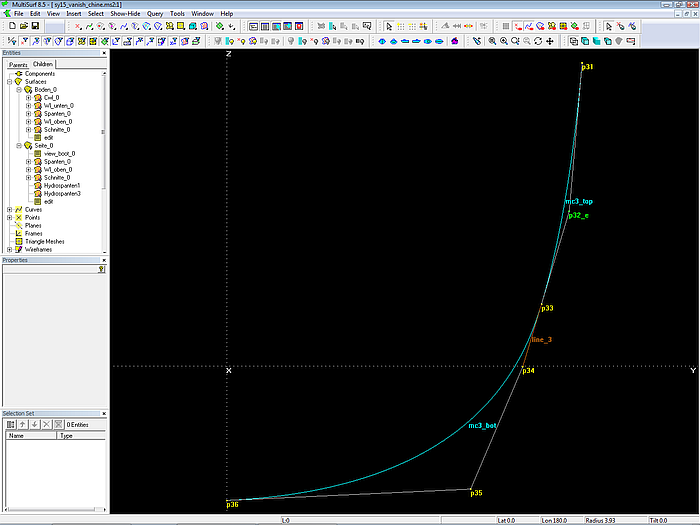
B-spline Curve mc3_top joins smoothly B-spline Curve mc3_bot, if their common cp p33 and its neighbours p32_e and p34 are aligned.
Why line between p33 and p34 and not between p32 and p34?
Right now the bead p32_e is beyond the upper end of the line (but still on the line).One may argue, that it would be more obvious, if the line runs from point p32 to point p34. Then the bead would be somewhere in the middle of the line.
The advantage of the chosen construction is, that a move of the bead will only effect the shape of the topside (mc3_top), the bottom (mc3_bot) is unchanged. Thus there is independency built in.
Further, the run of the chine is controlled by all the cp3 points. The chine is a prominent curve and as such must be directly editable. And not be altered in a side effect if a point aside is moved.
In other words - the topside is „fastened“ to the bottom. All the bottom mcs and their cps play a more important role in the hull design than the cp2 points of the topside mcs.
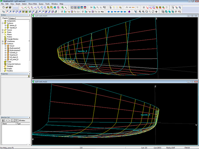
Vanishing chine - Wireframe 3D view of stern and bow.
Although the view of stations, waterlines etc. may look fine in Wireframe view at first sight, one should check the Render view too.
Here we can see, that the topside is linked fairly to the bottom at the location of mc2 and mc3, but not in the region between them.
Render view - topside and bottom show break between mc2 and mc3. Possible remedy: insert an additional mc.
This fault can be removed by a smaller y-coordinate of cp3 on mc4. i. e. decreasing the width of the chine at mc4. But let us assume, we do not want to change the bottom or the topside, they are just right. Then the solution is, that we must extra clamp the topside surface to the bottom surface in this region – as it would be done in practice.
In other words, we must add for the topside an additional mc between mc2_top and mc3_top.
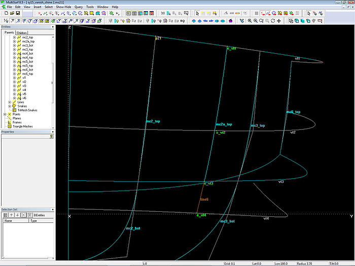
The cps of mc2a_top are determined as follows. We put a bead (Bead e_vl1) on the vertex curve vl1. This bead specifies the longitudinal location of mc2a_top. At the location of e_vl1 the vertex curves vl3 and vl4 are intersected (XYZBeads e_vl3, e_vl4). These two beads support a line, on which Bead e_vl2 resides.
Now the new B-spline Curve mc2a_top is supported by e_vl1, e_vl2 and e_vl3. Then the bead e_vl2 is added as cp of the vertex curve vl2. And finally mc2a_top is inserted as an additional mc to the topside surface. We clamp the topside smoothly to the bottom at the position of e_vl1.
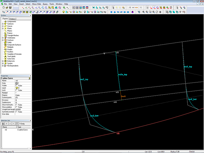
Extra mc for the topside surface in model sy15_vanish_chine2.ms2
Relational geometry construction for the 3 cps of the additional mc2a_top.
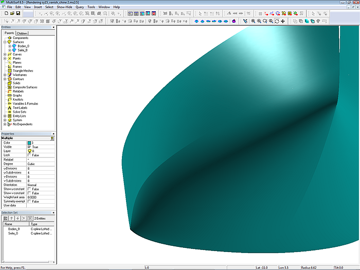
The chine vanishes fairly (model sy15_vanish_chine2.ms2).
Note the benefits of the Vertex Curve Method. The cps of the additional mc2a_top are not free points, which require tedious positioning to achieve surface fairness. Due to the relational geometry of MultiSurf all what one has to do is to slide e_vl1 along vl1 to position mc2a_top and move e_vl2 up or down its support line to make vl2 a fair curve.
Ship Lines view of sy15_vanish_chine2.ms2
Curvature Profile
One problem remains. The 3 forward mcs for topside and bottom are smoothly linked due to the alignement of corresponding cps. But is the distribution of curvature along both curves such as if it would be a single curve?
In order to check this matter for example with mc3_top und mc3_bot, we combine both into the Polycurve mc3_test and display its Curvature Profile.
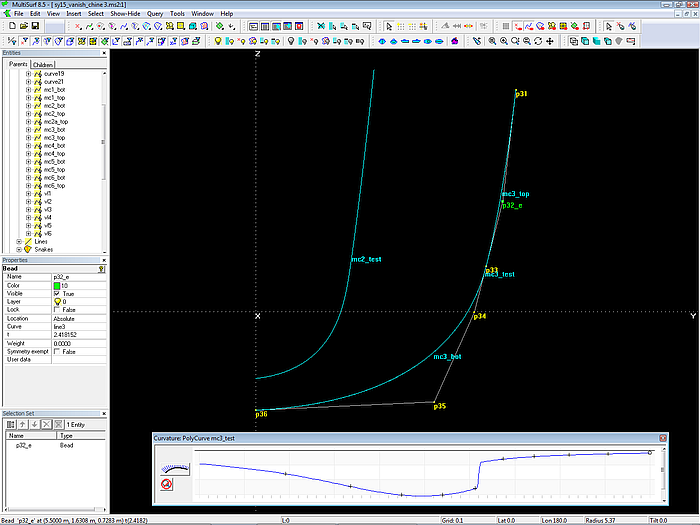
Disharmonic curvature distribution – there is a sudden increase at p33, where mc3_top ends and mc3_bot starts.
By moving the bead p32_e one can achieve a curvature distribution that resembles the one of a single continuous B-spline Curve of degree 3.
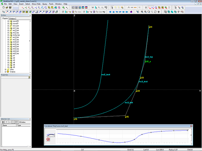
Harmonic distribution of curvature along PolyCurve mc3_test, which combines mc3_top and mc3_bot.
One cp more for the bottom mcs?
If we take a look how the cps are distributed along the bottom mcs, for example mc3, then we notice, that point p35 is rather far away from point p36. Therefore local control of the shape is low. In model sy15_vanish3.ms2 there is one cp more for the bottom mcs.