Chine-Form Powerboat Hulls
A further variation of the C-spline Lofted Surface theme
by Reinhard Siegel
Introduction
Powerboats show more complex hull shapes than sailing boats. Chines, steps in the topside, tunnels in the bottom, transverse bottom steps, to name a few geometry form properties.
In this article I would like to explain on the basis of the model pb10.ms2 how to create in MultiSurf a standard chine form hull for powerboats. This is not about making a hull with specific dimensions, but shows how the C-spline Lofted Surface can also be used advantageously for this kind of hull shapes.
Abbreviations used:
cp: control point (support point)
mc: master curve = support curve
cp1, cp2, ...: denotes 1st, 2nd, ... point in the list of supports of a curve. It is not an actual entity name.
mc1, mc2, ...: denotes 1st, 2nd, ... curve in the list of supports of a surface. It is not an actual entity name.
In the following the terms used for point, curve and surface types are those of MultiSurf. This may serve the understanding and traceability.
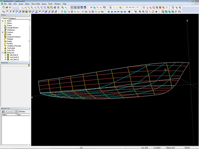
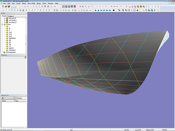
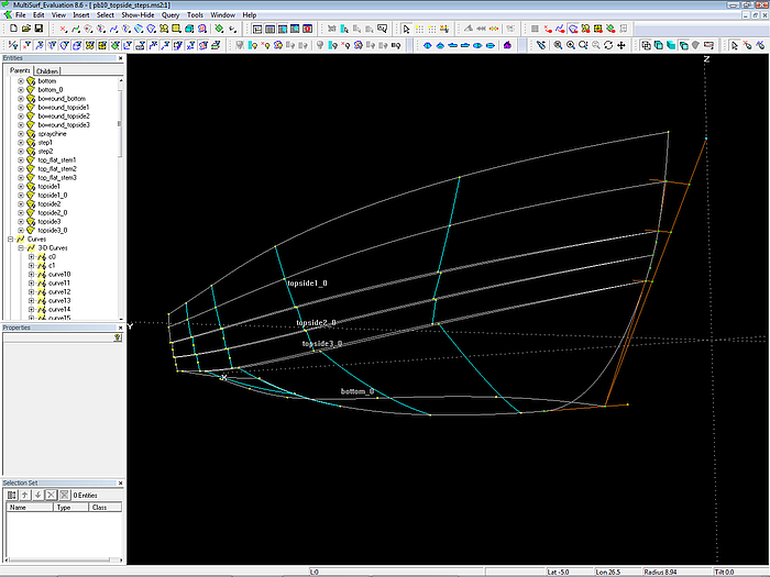
Model pb10.ms2 opened in MultiSurf. Wireframe view
Concept
The hull is composed of 2 surfaces, topside and bottom. Their modeling is analogous to the modeling of a standard round bilge hull.
Topside and bottom are created as C-spline Lofted Surfaces, each one supported by 6 mcs, all B-spline Curves, the degree is 2. The bottom mcs are supported by 3 cps, also the topside mcs.
The last cp of a topside mc also serves as 1st cp of the corresponding bottom mc. Thus the lower edge of the topside surface and the upper edge of the bottom surface coincide - the two-surface hull is watertight.
The 2 bow mcs (mc1_top, mc1_bot) are linked fairly. The other mcs of topside and bottom join with a break.
Vertex curves (C-spline Curves) pass through corresponding cps.
Why vertex curves?
Vertex curves are guiding curves for fairing a C-spline Lofted Surface. If vertex curves run in a harmonious, regular fashion, the surface is fair.
The Vertex Curve Method requires, that mcs are of the same kind (B-spline Curve) and each mc has the same number of cps. This requirements are satisfied.
Vertex Curve vl1 corresponds to the sheer, vl3 to the chine, and vl5 to the fairbody curve. They can easily be checked for fairness by using Display Profile/ Curvature.
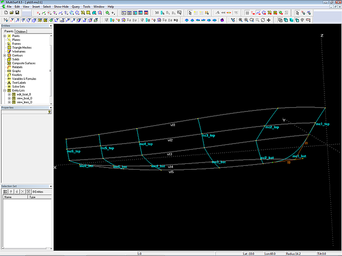
The C-spline Lofted Surfaces topside_0 und bottom_0 are each supported by 6 mcs. Vertex Curves pass through corresponding cps.
Why fairing in 3D view?
The hull surface must be fair. The Vertex Curve Method states: fair vertex curves make a fair surface. Thus the cps of the mcs must be arranged to make the vertex curves run smooth. This can be very well controlled by looking along the vertex curves in 3D view. One can rotate the model on the screen around any point and view obliquely along any curve. Just as if one had built a real model and would turn it in his hand back and forth. This way one can see any irregularity in the run of a curve, a waterline, etc.
Viewing along curves and contours in 3D is a powerful way to check fairness.
Why restricting the dragging of cps?
Moving a point in 3D view will usually change each of its 3 coordinates. This can be prevented by using the property Dragging of the Point entity.
For example, to ensure that all cps of mc3 to mc6 stay in their cross section planes, their Dragging property is set to (y and z). Now, when you move these points in 3D view, their x-coordinates do not change.
Further, all the last cps of the bottom mcs should end on the centerplane. Therefore their y-coordinate is set to 0 and dragging restricted to (z).
Why is mc2_top inclined?
Mc2_top is not in a transverse plane, its 3 cps are staggered. Cp1 is more forward than cp2, cp3 is aft of cp2. The reason is the distribution of curvature in the topside. The sheer is strongly bended in the bow region, so it needs support here. The chine is less curved, so its support can be further aft.
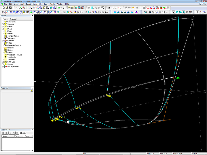
How to link mc1_top and mc1_bot smoothly
The bow should be a fair curve, thus the topside and the bottom mc must be connected fairly. To join two B-spline Curves with no break we use their tangency property. A B-spline Curve always starts tangent to the first segment and always ends tangent to the last segment of the polyline through its cps. Thus, if two B-spline Curves join, and the neigbours to the common point are in line, the transition is tangent.
This required relationship for the bow mcs is hardwired by a simple construction: a) a line is spanned between the 2nd cp of the top mc and the 2nd cp of the bottom mc, b) a bead on this line serves as 3rd cp of the topside mc and as 1st cp of the bottom mc, thus all 3 cps are aligned.
Note: hardwire required relations
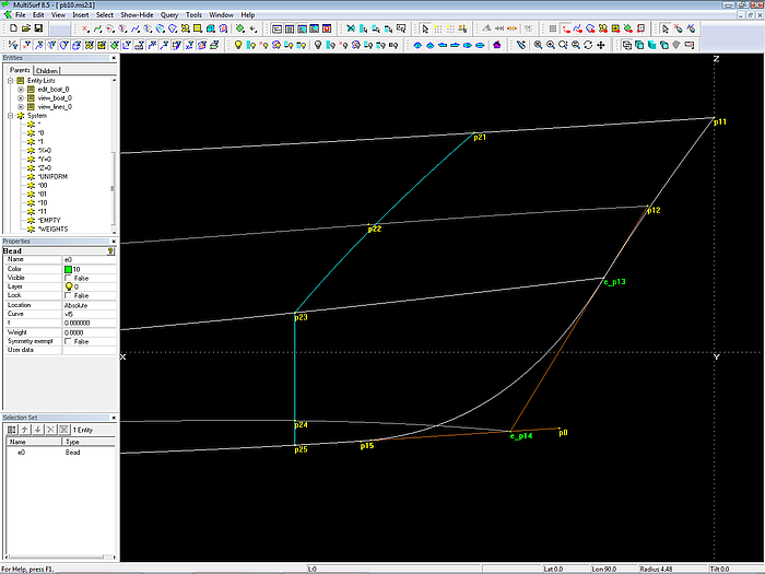
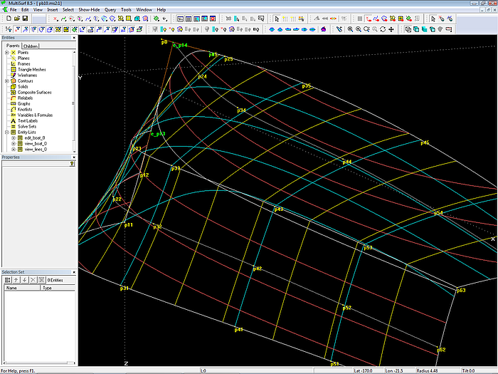
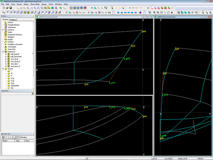
B-spline Curve mc1_top joins smoothly B-spline Curve mc1_bot, if their common cp e_p13 and its neighbours p12 and e_p14 are aligned. B-spline Curve mc1_bot ends tangent to the vertex curve vl5 because its second but last cp (e_p14) and its last cp (p15) lie on the tangent to the start of vl5. Wireframe view.
How the tangent entry of the bow into the fairbody curve is hardwired
The vl5 describes the contour of the profile (fairbody curve). The bow-mc must run without a break into the fairbody (except it is intentional). One can check by viewing this spot in 3D - zoom deeply in and turn the model until your view slides along the end of mc1 and the begin of vl5. And make a manual fix if needed.
However, this is not MultiSurf-like. Better we make use of the tangency property of B-spline Curves. First, create a line that is tangent to vl5 in its starting point (Line between cp3 of mc1_bot and a Tangent Point based on Bead at t=0 on vl5). Next create a bead on this tangent line and use it as cp2 for the bow mc of the bottom. With this construction the tangent entry of mc1_bot to the fairbody curve of the hull is hardwired into the model.
Note: hardwire required relations
Render view
How to add a bowround
So far the model has a sharp stem. All cps of its bow mcs (mc1_top, mc1_bot) are on the centerplane, their y-coordinates are 0. To add a bow rounding is not difficult, however. This is shown in the model pb10_bowround.ms2.
Concept
The bow mcs are moved a bit off the centerplane to form half siding curves. So topside and bottom surface start open at the stem. The gaps are then closed by flat surfaces, perpendicular to the centerplane. The arising edges are then rounded off by the bowroundings – starting with continuous tangency or curvature on the hull and ending anywhere normal to the centerplane (Blend Surface).
This approach is likewise to the work on the drawing board, where low and moderate curved parts of the hull were drawn with splines, and where the bend in the intented shape would break them, a ship curve was applied (the raw and cooked spagetti technique).
Step 1:
First move cp1 and cp2 of mc1_top off the centerplane. Note, that due to the built-in relations the tangency between the bow mcs is maintained, as well as the tangent entry of the bow into the fairbody curve.
Moving cp1 and cp2 of the topside bow mc off the centerplane opens the bow; all built-in tangency properties of the stem mcs persist automatically.
Step 2:
Create the edgesnake, that runs along the leading edge of the topside and project it onto the centerplane
Step 3:
Span a Ruled Surface between the edgesnake and its projection (flat stem)
Step 4:
Create edgesnakes along the outer and inner edges of the stem flat.
Step 5:
Create a snake on the topside surface where the bowrounding should start.
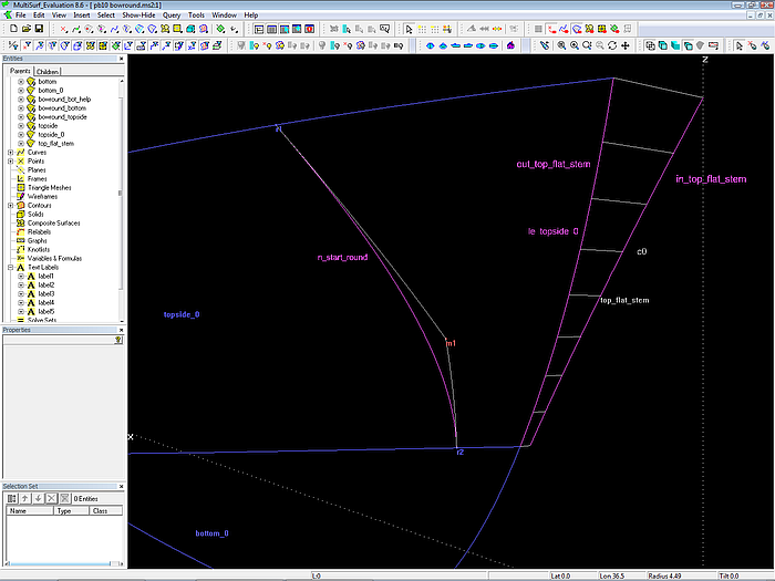
The forward edge (le_topside_0) of the topside surface is projected onto the centerplane (Projected Curve c0) and a Ruled Surface is spanned between them (top_flat_stem).
Step 6:
Create a Blend Surface using the start snake, the edgesnake along the leading edge of the topside surface and the 2 edgesnakes of the stem flat.
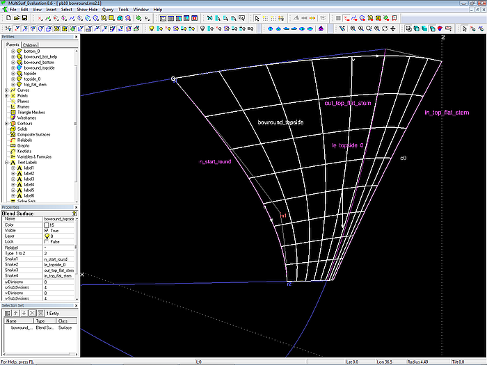
Bow rounding as Blend Surface; it agrees with topside_0 in curvature as well as slope (G2 continuity) at its start. It ends normal to the centerplane.
Step 7:
Make a SubSurface between the start snake of the bow round and the trailing edge of topside_0.
Repeat the previous steps for the topside bow rounding for the bottom surface.
Why projecting the edgesnake and not mc1_top?
Mc1_top is a support of the topside surface. It runs along its leading edge, but is not an edge curve on the surface. Only EdgeSnakes lie on surface edges. In the hierarchy of dependencies there is first mc1_top, then the surface topside_0, then the edgesnake. If we want to attach a stem surface to the topside, than it is according to the dependencies logical, to use the edgesnake.
Suppose, in a later stage, a different curve is used as mc1 for the topside surface. Then one must take care and edit also the bow rounding construction. Using the edgesnake the bow is adapted automatically.
Apart from this – if the construction of the model is analysed after some while, and you see, that one support of the Ruled Surface is an EdgeSnake, you simultaneously know, it will be joint watertight to a surface edge. If you see, the support is a free curve, you just know this, you do not have at the same time any further additional information about the geometry.
A Line entity is a line, it can only be straight. A B-spline Curve or a C-spline Curve can also be a line, but you only know this for sure, if you check and see, that there are just 2 cps. With a Line entity you immediately know what you can expect from it.
Note: the entity type simultaneously transports information about its geometric behavior. Clear information makes work easier.
The Blend Surface requires 4 snakes as supports, two snakes on surface 1, two snakes on surface 2. Snake1 defines the start of the rounding on surface 1, snake4 defines the end of the rounding on surface 2. The inner snakes (snake2 and snake3) control the shape of the rounding. Here snake2 is the leading edge of surface 1 (topside_0), and snake3 is the outer edge of surface 2. Since surface 1 and surface 2 share a common edge by construction, snake2 and snake3 are one upon another (but snake2 is on surface topside_0, snake3 is on the stem help.

Model pb10_bowround.ms2 in Render view
Adding a spraychine
The model gets more complex – create 5 points, 6 curves and 1 surface.
Concept:
So far topside surface and bottom surface share a common edge – because cp3 of the topside mcs is also cp1 of the bottom mcs (except bow). Thus, if cp3 is moved, both topside and bottom will change. By inserting an individual cp1 for the bottom mcs this link is removed. The gap between the lower edge of the topside surface and the upper edge of the bottom surface is closed by the spraychine.
Model pb10_spraychine.ms2. Topside and bottom mcs have individual cps at the chine. Their distance controls the width of the spraychine.
The spraychine surface is a Ruled Surface, which is spanned between two PolyCurves. The one PolyCurve is the combination of the lower edges of topside and topside bowround (edgesnakes). The other one is combined by the upper edges of bottom and bottom bowround (edgesnakes).
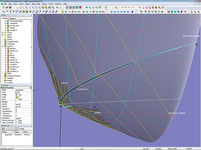
The Ruled Surface spraychine is spanned between the edges of topside and bottom surfaces. Shaded view
Why spraychine between PolyCurves?
The spraychine closes the gap between the bow roundings and the hull surfaces (topside, bottom). Either there could be the short piece of spraychine between the lower edge of the topside bow rounding and the upper edge of the bottom bow rounding. And a long strip between the the lower edge of the topside and the upper edge of the bottom. Or there could be one single piece of spraychine supported by a combination of edgesnakes of the corresponding surfaces.
I prefer the latter, it is a matter of personal preference – the short piece could easily be forgotten, for example when creating contours.
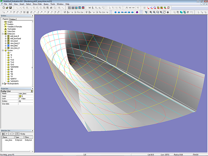
Model pb10_spraychine.ms2. Render view
Adding topside steps
While we are adding features to the model, how about a step in the topside? It may serve as stiffener, spraychine, design mark.
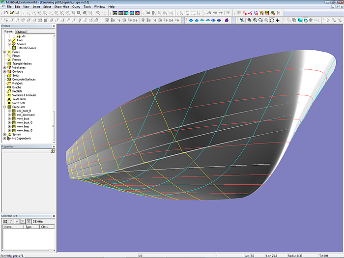
Model pb10_topside_steps.ms2 in Render view
Concept
The multi-surfaced topside is split along the step edges into longitudinal strips. Those horizontal oriented ones are created likewise to the spraychine (Ruled Surface). Those vertical oriented ones are another application of the C-spline Lofted Surface. Each vertical strip has its own bow rounding (Blend Surface).
The topside is split into 3 stepped surfaces (oriented vertical), each a C-spline Lofted Surface on B-spline master curves.
Towards the stem the steps vanish. This requires, that the 1st mcs of the topside surfaces join smoothly. For this we utilize again the tangency property of the B-spline Curve.
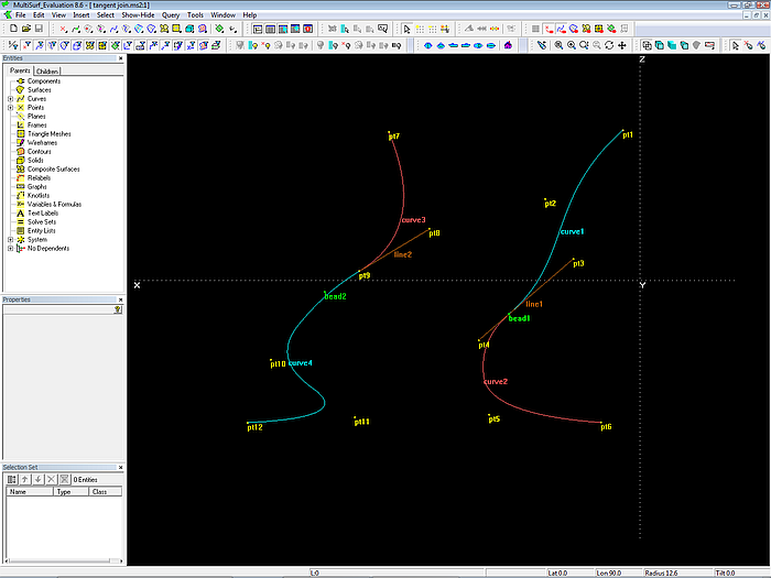
Principle of joining two B-spline Curves smoothly: the common cp and its neighbours must be aligned.
Curve1 and curve2 share the common cp bead1, which is on the line between pt3 and pt4. In this construction the common cp will change its location if pt3 or pt4 is moved.
Curve3 and curve4 share the common cp pt9, its neighbours are pt8 and bead2. The latter is on the line between pt8 and pt9 (although beyond the end of the line). In this construction the common cp is free to position.
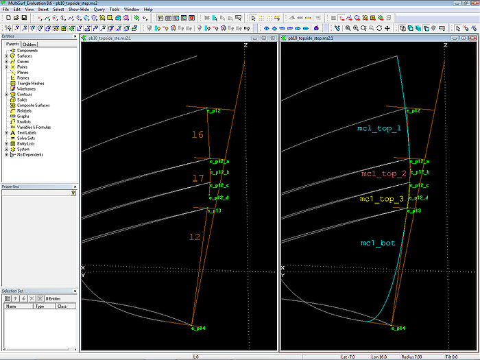
Underlying construction of the smooth join of the bow mcs of the topside surfaces. Bead e_p12_b is on line l6, bead e_p12_d is on line l2, and bead e_p12_c is on line l7.
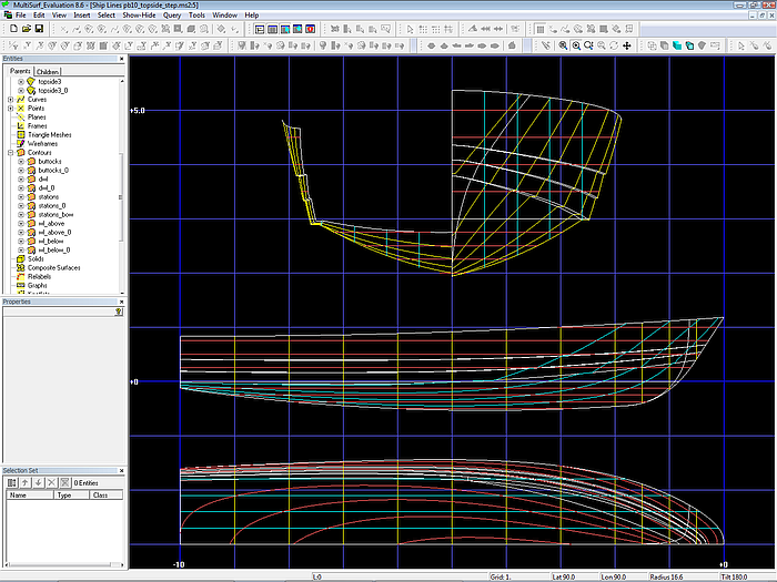
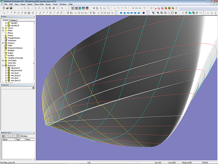
Ship Lines view of model pb10_topside_step.ms2
Render view of model pb10_topside_step.ms2
So far to the basics of modeling hull forms using the C-spline Lofted Surface.
In the next article a comparison is made to its relative, the B-spline Lofted Surface.