The use of components for the modeling of 2D structural parts in hull construction
On the creation of a frame in the aftbody of a metal powerboat
by Reinhard Siegel
Introduction
Let us assume we have made the geometry of a standard metal powerboat: surfaces for hull and deck. And we went beyond this ordinary extent and have also added a series of longitudinal frames (stiffeners) to support topside, bottom and deck. Next we would export sections and continue in a cad program in order to define all the flat structural parts required for the construction of the boat. But this means: the world of relational geometry is left. If there will be any change of the model, the cad drawings must be adapted. And certainly, there will be changes. In the following it is shown by the example of a transverse frame, that there is no need to leave MultiSurf for the creation of complex flat parts.
Recuring tasks
The definition of the outline of a metal boat web frame requires recuring drawing of
- cutouts for longitudinal frames
- cutouts for welding, limberholes
- parallel curves
- arc fillets between 2 curves
For these drawing work components are developed and repeatedly used.
The boat
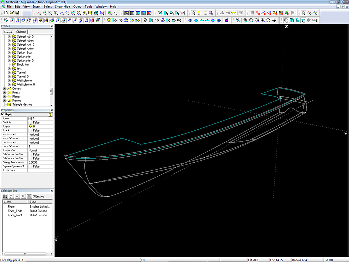
Model pb10-0.ms2 - a standard powerboat. The hull bottom features a propeller tunnel.
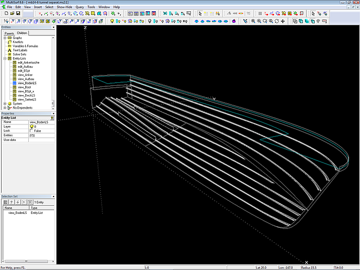
Longitudinal frames (stiffeners) on topside and bottom shell (Sweep Surfaces)
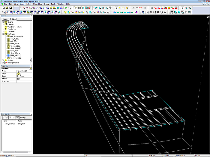
Longitudinal deck frames (Sweep Surfaces)
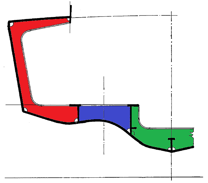
Aftship web frame – intended design
Step 1 – adding the frame basis
Frame basis – rectangular planar B-spline Surface
The basis for the web frame is a B-spline Surface, supported by 4 control points (cps). Point 1 is on the centerplane at the frame location. Point 2 and 3 are relative, defining width and height. Point 4 is a Copy Point, ensuring both rectangular and planar property.
Step 2 – cutting hull and longitudinal frames
Surfaces for topside, bottom, deck and stiffeners are intersected by the frame basis (Intersection Snakes). Using the “Copy” feature we can create a series of intersections in one stroke.
These intersections are projected onto the frame basis (Projected Snakes). Again, “Copy” speeds the creation greatly.
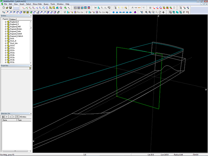
The frame basis cuts hull, deck and longitudinal stiffeners (Intersection Snakes, magenta). The intersections are projected onto the frame basis (Projected Snakes, yellow). Modell pb10-1.ms2.
Step 3 – stiffener cutout components, scallop component
Next we create cutouts for the longitudinal stiffeners. Their shape depends on the stiffener cross section and what is considered useful, practical, suitable. Here the cutout for hull stiffeners and deck stiffeners look like this:
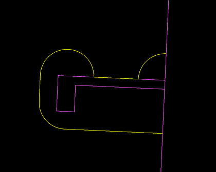
Cutout in the frame basis for longitudinal hull stiffener
Cutout in the frame basis for longitudinal deck stiffener
Since a series of cutouts is required, we create 2 components. This is the model for the cutout component for hull stiffeners:
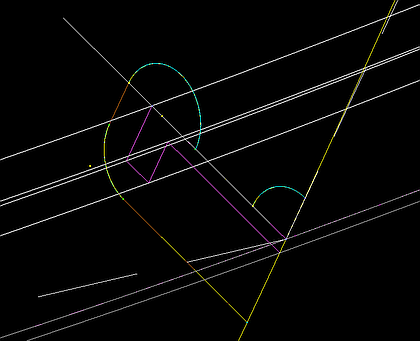
Model for cutout component (hull type)
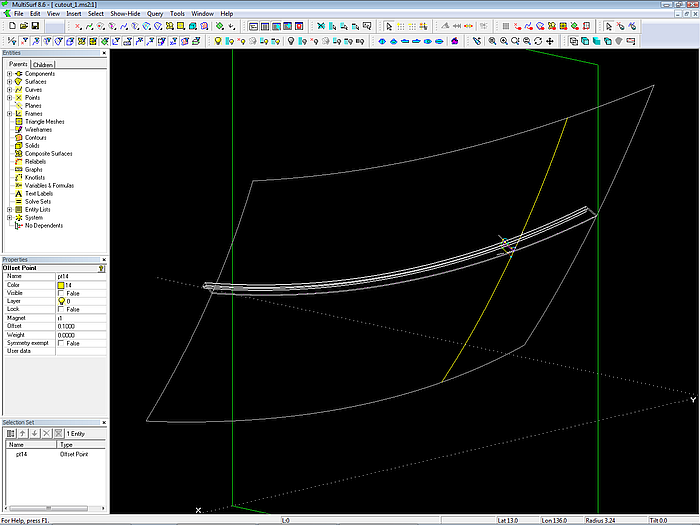
Model for cutout component (hull type)
This is the model for the deck stiffener cutout component:
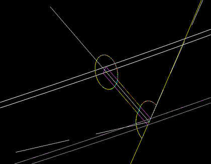
Model for cutout component (deck type)
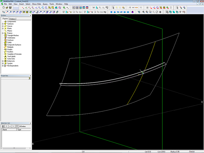
Model for cutout component (deck type)
Parents for both component are:
- the frame basis
- the hull (deck) cross section (snake on frame
basis)
- the stiffener cross section
Products of both components are:
- the cutout shape as Projected Snake on
the frame basis
- rings on the hull (deck) cross section, located at the start and at the end of the coutout. These rings will be used lateron for SubSnakes, when creating the frame outline boundary.
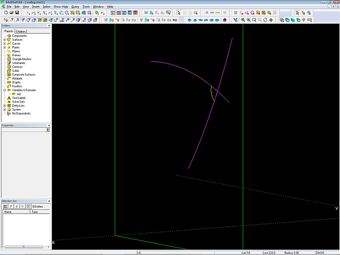
Scallop component
The scallop component is quite simple. The intersection point of two snakes on the frame basis is the center of an arc. Start and end of the arc are Intersection Rings, where Mirror/ Surface is that point of intersection of the two snakes, thus the cutting object is a sphere.
Parents:
- the frame basis
- a ring on each of the two snakes on the frame basis
Products:
- the scallop shape as Projected Snake on the frame basis
- rings on the snakes, where the scallop starts and ends. These rings will be used lateron for SubSnakes, when we create the frame outline boundary.
Parameters:
A variable for the scallop radius
Step 4 – create cutouts and scallops by components
Cutouts by components. All relational. Move the frame basis and everything adapts. Model pb10-2.ms2.
Using the previously introduced components it is now easy to add the cutouts and scallops to the frame basis.
Step 5 –parallel curve component and arc fillet component
The web frame at the side of the hull has a constant width. So we need to create for it a parallel curve to the hull section. Again this is a recuring task, and thus calling for another component.
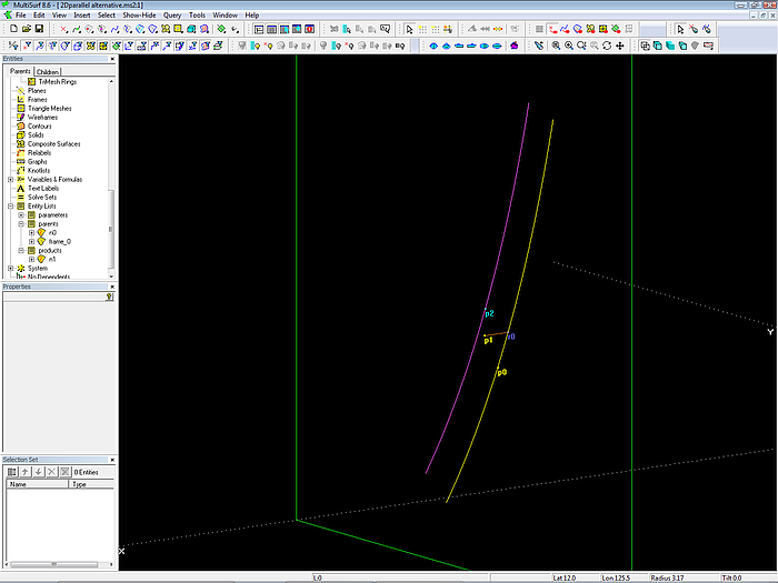
The entities of the component 2D_Parallel.mc2
The component principle is this: situated on the basis curve is Ring r0; p0 is a Tangent Point to r0, its offset is equal to the offset of the parallel curve. p0 is rotated by 90° around a line which is perpendicular to the frame basis and passes through r0. The result is Rotated Point p2, which is then projected onto the frame basis as Projected Magnet m1. This is one point of the wanted parallel curve. With a Procedural Snake this construction is repeated for all positions of Ring r0.
Parents of the component 2D_Parallel.mc2 are:
- the frame basis
- a snake on the frame basis
Product of the component is:
- the parallel curve as Procedural Snake on the frame basis.
Parameters:
The parallel offset is set by a variable.
Another common task is to round the edges of 2 curves by an arc. For this purpose serves the component 2D_ArcFillet.mc2.
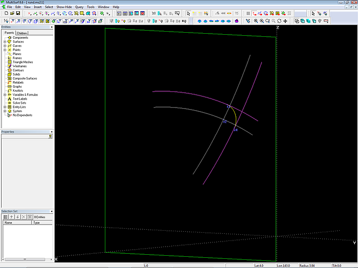
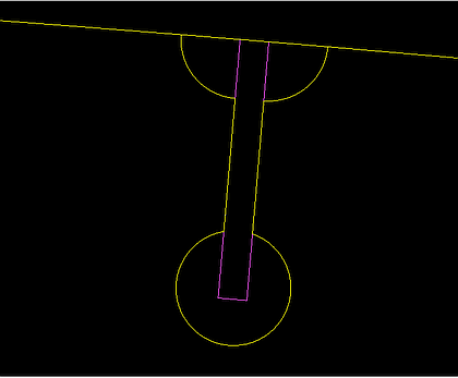
Component 2D_ArcFillet.mc2: it rounds 2 snakes (magenta) by an arc (yellow)
The idea is this: center of the arc is the intersection point of the 2 curves, that are parallel to the basis snakes, their distance being the arc radius. Begin and end of the arc are the points on curve 1 and 2 closest to that center point (Proximity Rings).
Parents of the component 2D_ArcFillet.mc2 are:
- the frame basis
- 2 snakes on the frame basis
Products of the component are:
- the arc fillet
- rings on both snakes, where the arc starts and ends (to be used for trimming SubSnakes)
Parameters:
The arc radius is set by a variable.
Step 6 – adding flesh
Web frame at hull side added by component 2D_Parallel.mc2. LineSnakes added for deck beam knee and floor heights (model pb10-3.ms2)
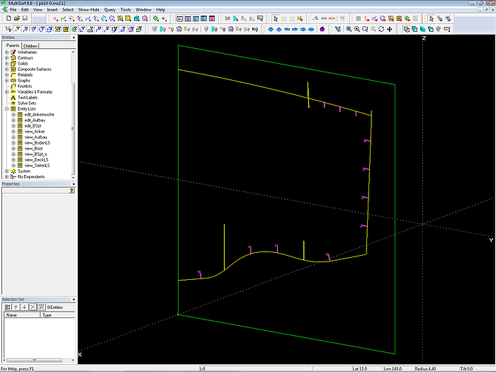
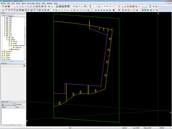
Arc fillets added by component (model pb10-4.ms2)
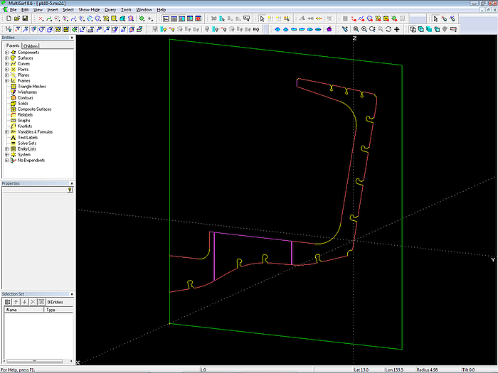
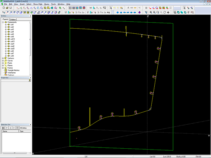
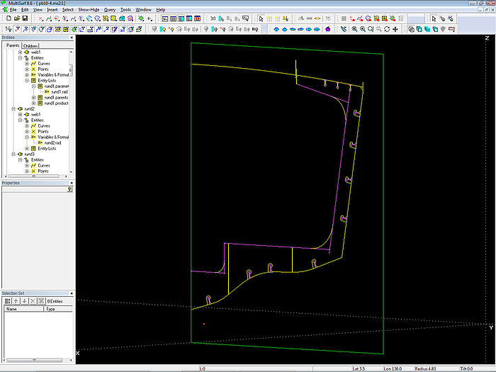
Frame outline. Adding SubSnakes for the boundary is easily done due to the rings on the adjacent snakes, which are created by the components for cutouts, scallops and arc fillets. Complete relational construction. If there is another frame of the same kind, the frame basis and all its children can be saved as a component and inserted again. (model pb10-5.ms2)
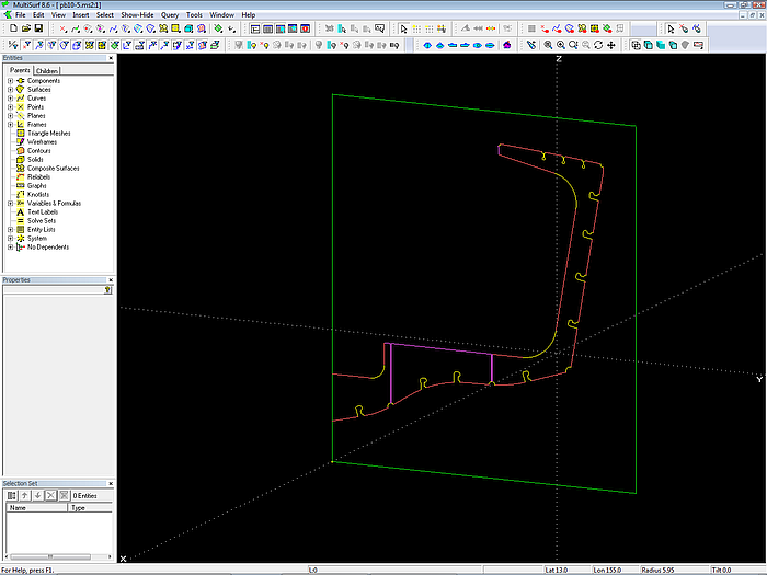
Web height and arc fillet radii modified; dimensions controlled by variables (model pb10-5.ms2)
Tips for making components
- Make the model, which creates the wanted entities, as simple as possible. If it contains only the necessary things it will be easier to understand how it works - for you and possibly for others.
- Make an Entity List for parents: this gives you immediate information what entites are provided from the reciving model.
- Make an Entity List for products: it should contain only the final entities, giving you immediate information about what is added (the intermediately created ones are necessary but of no direct interest).
- Make an Entity List for parameters: it will give you direct information what parameters of the geometry can be changed by what point and variable.
- If you have Entity Lists for parents and products, use the wonderful command “SelectForComponents”. It will add everything necessary to the Selection Set.
- And very important because very convenient: add to those required entities the Entity Lists for parents, products and parameters. So, once you have loaded the component into a model, you will have quick access to very valuable information. Select the component in the Entities Manager, and navigate to its Entity Lists: here you see what are the parents, what are the products, and what parameters are available to control its geometry.
Tips for loading components
- If you load a component repeatedly, use the shortcut Alt + L to go directly to the Load Component File Open dialog window.
- Preselect the parents for the component to load. In the Load Component/ Resolving Parents dialog window the selection of parents via the list box is inconvenient: the box is too short, it displays just 6 lines, although the window can be extended downwards. And there is no sort by name and type, so you will have to scroll up and down through many entities until you find the proper ones – if at all you know their names.