On Modeling Classic Sailing Yacht Hulls
Some variations of the round bilged hull theme
by Reinhard Siegel
Introduction
The hull shape of a classic sailing yacht is more complex than the hull of a modern sailing boat: long bow and stern overhang, full, easily turned garboards, rudder attached to keel trailing edge as a flat piece or being part of the keel surface as a flap. Boats of the Dragon class, meter class yachts or traditional long keel sailing cruisers are examples of the hull type in question.
This article has in view to show methods how to create classic yacht hull forms in MultiSurf. It is not about designing a hull with specific dimensions and shape, but explains the pros and cons of various procedures, so in the end you can decide which method will suit your needs best.
Classic sailing yacht hull – 30 square metre yacht
Abbreviations used:
cp: control point (support point)
mc: master curve = support curve
In the following the terms used for point, curve and surface types are those of MultiSurf. This may serve the understanding and traceability.
A general remark before start:
The models shown in the following here are evidence of the author´s preference to creatre hull surfaces by the C-spline Lofted Surface with B-spline master curves (control curves). A hull is typically low curved in longitudinal direction, and highly curved athwartships. C-spline Curves are stiff, like raw spaghettis. B-spline Curves bend easily, like cooked spaghettis. Thus lofting stiff C-spline Curves onto soft B-Spline master curves appears a logical way to copy the proven practice of building boat hulls by running planks over a series of moulds.
Method 1: one surface for all
Transom stern hull
Model classic-1.ms2 shows the application of the standard round bilge hull method for a transom stern boat.
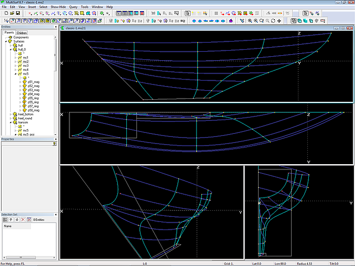
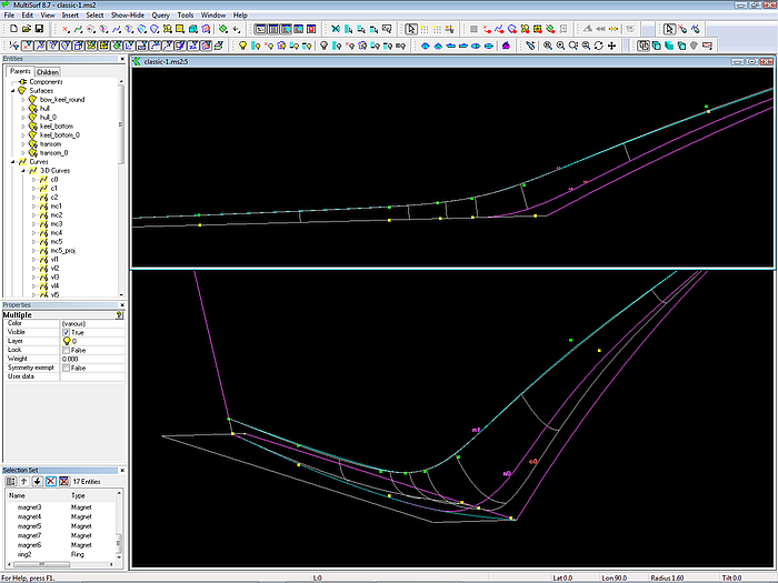
Model classic-1.ms2: transom stern hull (C-spline Lofted Surface on B-spline mastercurves)
5 B-spline mastercurves (mcs) support the C-spline Lofted Surface. All mcs are of the same degree (3) and each is defined by 8 control points (cps). Thus C-spline Curves can be passed through corresponding cps to serve as guiding curves for fairing (vertex curves),
Why vertex curves?
Vertex curves are guiding curves for fairing a surface. If we make them run in a harmonious, regular fashion, the surface is fair. For a C-spline Lofted Surface the vertex curves are C-spline Curves, passing through corresponding cps.
There are two prominent vertex curves for C-spline lofted hulls: the one through all the first points of the mcs – the sheer curve; and the one which is supported by all the last points of the mcs – the fairbody curve. The complexity of either sheer or fairbody decide how many mcs are required and where to position them in order to get the wanted surface shape.
The bow mc (mc1) defines the stem of the hull including the leading edge of the keel. Its cps are all on centerplane, thus mc1 is actually the bow ghost line. Also mc1 ends angular at the keel bottom, it does not include a rounding at the keel forefoot. Therefore a bowrounding is to be added.
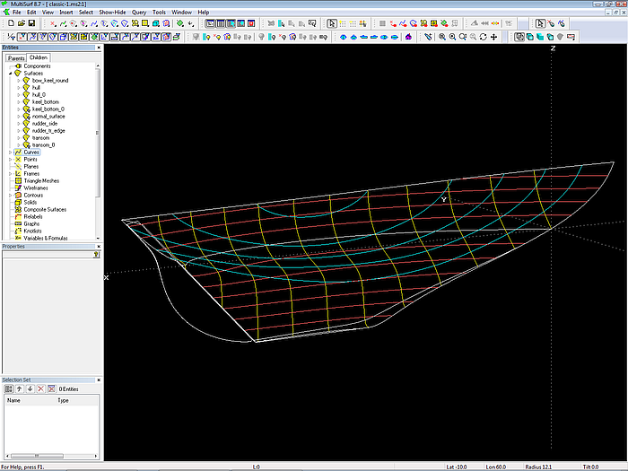
Model classic-1.ms2: system of mcs and vertex curves. The cps of mc5 are magnets on the transom surface.
Since crossing mastercurves will produce a surface with wrinkles, mc2 runs obliquely from the sheer down to the keel tip. Thus there is just an indirect relationship between its shape in body plan view and the shape of stations in the foreship. Remember, that a C-spline Lofted Surface is supported by its mcs in the same way as the planks of a real clinker or carvel built boat are held fixed in space by its framework.
The main station is defined by mc3. Its upper cps have the same x-position, so the shape of the mc is the station shape.
Similar to mc3 the upper portion of mc4 runs transversely; further down it bends forward, avoiding to get too close to mc5 – nearby running mcs are prone to cause unfairness in the surface.
In order to keep the stern mc (mc5) straight in Y-view, its cps are no free 3D points, but magnets on the flat transom surface raked aft. This allows to move the cps freely around in any view until the mc looks ok, without the necessity to pay attention that all points are in a common plane.
In the same way the end cps of mc2, mc3 and mc4 are magnets on the flat keel bottom surface. With the help of those base surfaces the cps can be moved around arbitrarily, but the corresponding curves remain always straight in profile view.
Bow-Keel Rounding
As said above, mc1 entirely runs on centerplane, thus waterlines will cut the water. In order to round the entry of the keel waterlines and as well as the corner between leading edge and bottom of the keel a rounding surface is added. This is a B-spline Lofted Surface on 3 supports:
- the B-spline Curve c0; it defines the wanted profile outline; it runs on centerplane first, then continues on the keel bottom surface.
- the Projected Snake n0; it is the projection of c0 onto the hull surface normal to the centerplane. Thus in Y-view both c0 and n0 are one upon another. This hardwires that the bow-keel rounding starts normal to the centerplane anywhere.
- the Projected Snake n1; it is the projection of the B-spline Curve c1, which defines the end of the rounding.
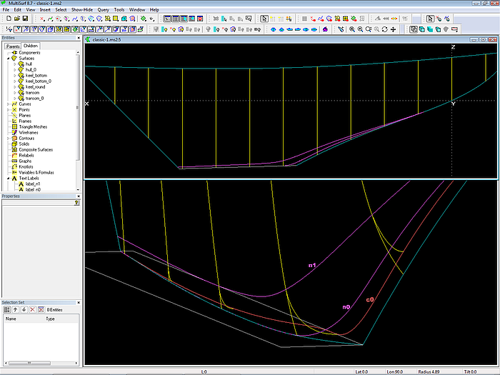
Control curves of the bow-keel rounding. B-spline Curve c0 runs first on centerplane, then curves down to the keel bottom; it defines the start of the rounding B-spline Lofted Surface; n0 is the projection of c0 onto the hull surface. Snake n1 defines the end of the rounding.
Note, that B-spline Curve c0 bends away from the centerplane when reaching the keel bottom; thus the rounding surface leaves a portion of the bottom flat.
Why is n1 a Projected Snake?
It is obvious, that n0 must be a Projected Snake of the profile curve c0 - a point on n0 will just have some y distance with regard to the corresponding point of the same parameter value t on n0. So all the lofting curves of the rounding B-spline Lofted Surface start normal to the centerplane anywhere.
But why is n1 also a Projected Snake, its parent curve being the B-spline Curve c1?
The reason is this:
The shape of snakes of the type B-spline or C-spline is affected by the shape of the u-v-parameter curves of the surface they lie on. You may carefully position control magnets and rings and yet discover, that those snakes tend to run by their own logic. Instead of fiddling around with more and more magnets to get hold on them, it is much easier and faster to create first a B-spline or C-spline Curve supported by magnets, and then project it onto the surface using the Projected Snake entity. Thus the influence of the distribution of the u-v-parameter curves of the parent surface on the curve shape is avoided.
Why use a B-spline Curve for c0?
A B-spline Curve is “soft”, easy to free-form with few cps, always close to the polyline through its cps; if some cps are aligned, the curve is partially straight. And B-spline Curves provide their tangency property: they always start tangent to the first segment and always end tangent to the last segment of the polyline through the cps.
c0 forms the profile of bow and keel leading edge. It starts somewhat below the design waterline at Ring r1; its second cps is a Tangent Point based on Ring r1, thus tangency is hardwired. c0 rounds the corner between leading edge and bottom of the keel. Using magnets on the base surface of the keel bottom ensures that c0 is running tangent into the keel bottom surface while being straight in profile view.
A related grouping of the cps produces a similar labeling of the B-spline Curve c0 and c1(yellow cps are supports of c0, green cps are supports of c1). This results in a regular distribution og the lofting curve and finally in a fair surface (u-constant parameter curves of the rounding B-spline Lofted Surface are shown in grey color).
Why use a B-spline Curve also for c1?
Answer: to achieve a regular distribution of the u-v-parameter curves of the bow-keel rounding surface.
Explanation: here a B-spline Lofted Surface is used for the bow-keel rounding. Any kind of lofted surface is generated by the same procedure: on each of the control curves or mastercurves MultiSurf locates points at the same parameter value t, then uses the resulting series of points as the control points for the lofting curve.
And now the labeling of the mcs comes into play. Labeling refers to the distribution of the t-parameter of a curve (think of each point of a curve as being labeled by a specific value of t). Although t is equal at each mc, the actual location of the corresponding cps can be different in direction of the run of the mcs.
If c0 and c1 are curves of the same type and same number of control points, and the control points are positioned with regard to each other, than their labeling is similar. And because a Projected Snake inherits its labeling from its parent, the labeling of n0 and n1 of the rounding surface is similar too. With the final result, that our B-spline Lofted Surface looks orderly.
Note: A surface with orderly running u-v-parameter curves is fair. But remember however, that a surface with disordered mesh can be fair nevertheless.
Control of curve labeling
The use of B-spline Curves of equal degree, equal number of cps and a related arrangement of corresponding cps is one method to control curve labeling. MultiSurf also offers special means to control the labeling of any curve type, for example by the curve type SubCurve, the Relabel entity or by relabeling with respect to arc length via Procedural Curve.
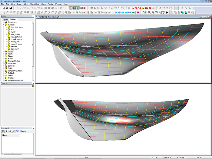
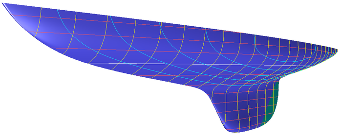
Render view of model classic-1.ms2
Colin Archer type hull
Another example of the standard C-spline Lofted Surface approach is model ca14.ms2, a Colin Archer type hull. 7 mcs control the hull surface, each a B-spline Curve of degree 3 with 5 cps. The first and the last mc is parallel to the centerplane (at half breadth of stem and stern member), running down from the sheer to the top of the keel. The inner mcs are transverse, except mc2, which supports the forward surface portion by running oblique - it should not come too close to the bow mc to avoid unfairness.
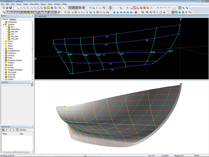
Model ca14.ms2: Colin Archer type hull - basic framework of mcs and vertex curves
Canoe stern hull
Some changes to the mastercurves, notably to the last one, and we get a classic hull with long stern overhang – model ky-1.ms2. 7 mcs control the hull surface, each a B-spline Curve of degree 3 with 7 cps. The first and the last mc define the shape of stem and stern; only mc4 in the mid runs transversely.
This construction also allows the use of vertex curves, the guide curves for fairing. However, most of the inner mcs must run oblique in space to give adequate support to the lofting C-spline curves. Thus there is no direct relation between station shape and mc shape. What makes modeling to a given set of lines on paper more difficult, for example.
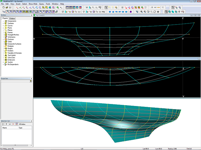
Model ky-1.ms2: long canoe stern – mc and vertex curve arrangement
Counter stern
How about cutting off the canoe stern by a transom? This is shown in model sk-1.ms2. By extending sheer and fairbody a virtual canoe stern is formed, so the basic surface can by constructed as in the previous model. It is finally trimmed against the transom surface.
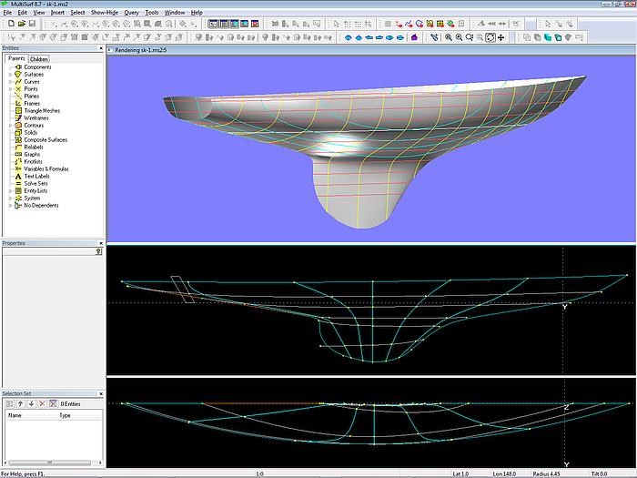
Model sk-1.ms2: system of mcs and vertex curves. The extended base hull is trimmed against the transom.
Passive control points
In a C-spline Lofted Surface the lofting curve is a C-spline Curve, the mathematical formulation of a batten curve. A real batten can break, but given a sufficient number of cps a C-spline Curve can be bent into any shape (except breaks in slope). Transfered to the lofted surface this means: given enough mcs any shape with continous longitudinal slope is possible.
This approach is used in the model RWS28.ms2, a 28 ft wooden schooner hull (by courtesy of Edward Stanley, AeroHydro Inc.). The mcs define the hull surface from the sheer to the rabbet curve. Except the one for the bow the B-spline mcs run transversely. Each is supported by 8 cps, so vertex curves can be drawn.
Obviously the most complex curve is the rabbet (vertex curve 8): it runs straight along the keel, so does the stern overhang, and there is quite some curvature when bending away from the keel towards the rudder post. To shape the rabbet to the wish of the designer it takes 16 points (red colored points in the screen image). Note, that some points are closely spaced, especially at the begin or end of areas of high curvature, in order to avoid oscillation. 16 points for the definition of the rabbet curve means 16 mcs.
In comparison the sheer curve is more simple. 11 cps can define it (4 of them are close nearby at the stern to bend the sheer continuously into the transom top edge). Thus we have the situation, where one prominent curve requires many mcs, the other one considerably less. The trick in this model is to create vertex curves just with the individually necessary number of points: 8 cps are used for vertex curves 2 through 6, curve 7 is based on 10 points. The fore and aft position of all these cps correspond to those for the rabbet curve.
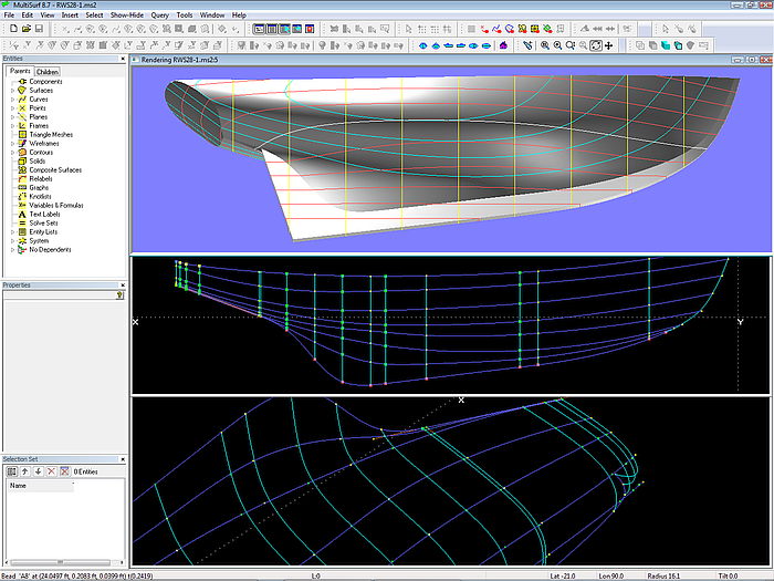
28 ft schooner (by courtesy of Edward Stanley, AeroHydro Inc.): system of master curves and vertex curves. Although the C-spline Lofted Surface is supported by 16 mcs, about half of the cps are Intersection Beads on the vertex curves, thus are automatically positioned.
It is obvious to refer to these points as active cps. In contrast to the passive cps (green colored points), which are derived by intersecting the vertex curves at the respective mc position. So we have a system of many mcs, but some of them have just one or two active cps, all their other cps are Intersection Beads on the vertex curves. Only the active cps need to be positioned by the user in order to form the mcs and at the same time keep the vertex curves fair.
Many mcs does not necessarily mean expensive adjustment of many cps. The use of vertex curves - with the minimum of cps required to achieve the wanted local shape - in combination with passive cps saves much work.
Stern mc by PolyCurve
What about making the last mc a combination of two parts – the one component A describes the stern shape transversely, the other component B runs down the fairbody curve to the aft end of the keel? A PolyCurve entitiy will combine curve A and curve B. This idea is investigated in model ap-1.ms2.
Obviously the PolyCurve will show a discontinuity in slope where curve A ends and curve B starts, a corner or breakpoint in simplier words. Due to this breakpoint the C-spline Lofted Surface shows a breakline in its u-v-parameter curves. And this has a detrimental effect on the surface fairness. One can try to adjust the end t-value for curve A in the properties of the PolyCurve entity, but this will often be not sufficient. However, with relabeling the neighbour mcs, what shifts the lofting C-splines along them, it should be possible to fair the problem area.
However, this PolyCurve approach for the stern mc does not allow the use of vertex curves. Apart from giving the mcs the wanted shape by positioning cps, there are two more variables: end t-value and relabeling. Each edit in the cps will require an edit of t-value and/ or relabel. Quite a bit of trial and test.
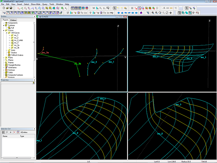
Model ap-1.ms2: mc3 is a PolyCurve, combining the transverse part mc_3a and the athwartship part mc_3b. The discontinuity of mc3 is reflected in the surface shape. The setting of the end t-value of the PolyCurve can improve the situation (lower left: t= 0.55; lower right: t = 0.4). Relabeling mc2 should further improve fairness.
Partly open stern mc
If the stern mc cuts the corner the discontinuity in slope is avoided. This idea is demonstrated in the model schooner_Fenwick.ms2. Its basic surface is a C-spline Lofted Surface on 5 mcs (B-spline Curves). The cps 1, 2 and 3 of the stern mc MCE have a common x position, while the remaining cps are at a common distance from the centerplane. Thus MCE first runs transverse and then curves forward to continue longitudinally parallel to the centerplane. However, this leaves a portion of the stern overhang open, since the basic surface will end at MCE everywhere.
To close the gap MultiSurf´s capability to extend a surface beyond its nominal limits is used. First, a magnet is placed aft of MCE, being support of a UVSnake which runs in the u-direction. Then a SubSurface is spanned between the bow of the basic surface and that UVSnake. It is similar to planking a hull but let them extend beyond the last mould. Next this SubSurface is trimmed against the transom and the centerplane.
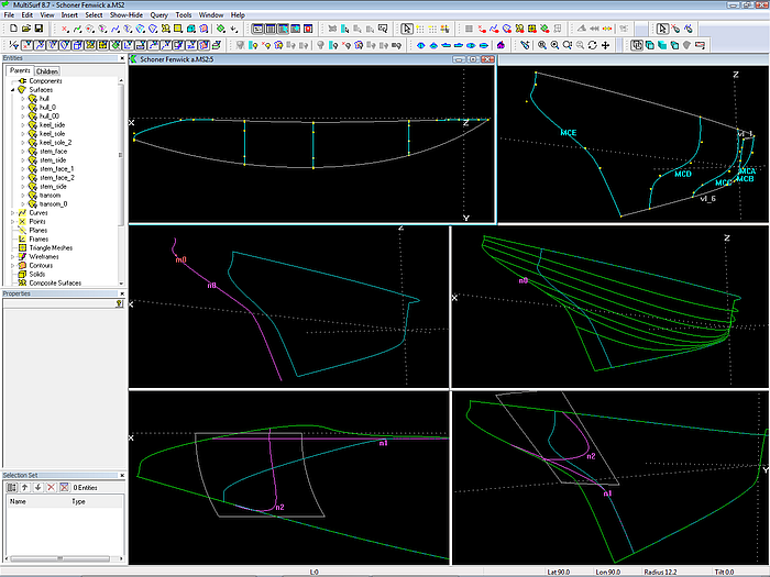
Model schooner_Fenwick.ms2. Top row: mcs arrangement of basic hull surface. Stern mc MCE is partly transverse, partly longitudinal. Mid left: UVSnake n0 beyond the nominal boundary of the basic surface. Mid right: SubSurface from bow to the UVSnake – natural extension of basic surface. Bottom: SubSurface intersected by transom and centerplane offset.
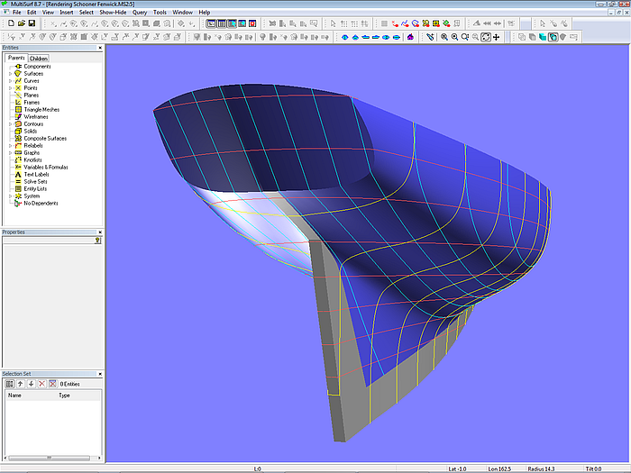
Model schooner_Fenwick.ms2
The advantage of this concept is the possibility to make use of vertex curves. And to describe a good deal of the stern cross section shape as well as a portion of the sternpost directly.
Side step:
Suppose, you have a finished model of a hull and for some reason (for example, a change in the position, rake or curvature of the transom) it must be extended aft - no extra change in form, just a natural continuation of the lines. Then the foregoing method to extend a surface by using a UVSnake beyond the nominal boundaries of the surface is also very useful. Put a magent on the basis surface beyond its aft end, pass a transverse UVSnake through it and create a SubSurface between bow edge and UVSnake. Finally adopt the children of the basis surface by the new SubSurface (main menu/ Tools/ Adopt Children).
Stern mcs partly beyond centerplane
Suppose you build a carvel or clinker hull and you do not cut off the planks at the stern, but let them extend beyond the centerplane. To give them support you also extend the aft moulds beyond the centerplane. The model long_counter.ms2 is based on this idea.
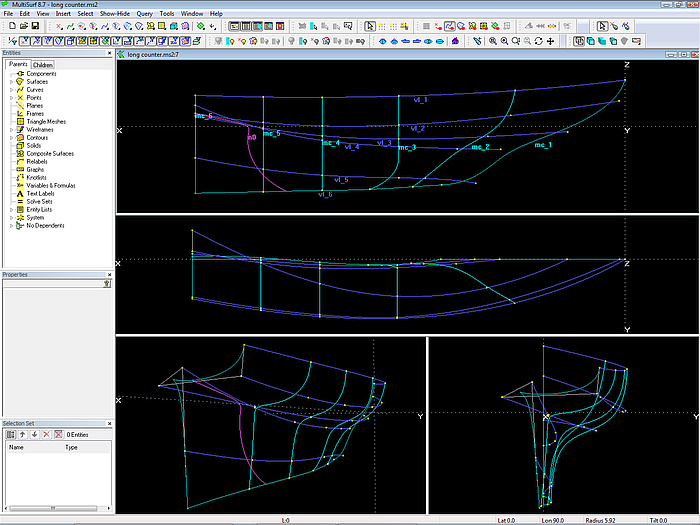
Model long_counter.ms2: system of mcs and vertex curves. Note, that mc5 and mc6 run partly on the negative side of the centerplane. The Intersection Snake n0 bounds the portion to trim off.
The advantage of this approach is twofold:
- it is possible to use vertex curves.
- mcs run transversely – mc shape is section shape.
The disadvantage is
- the indirect definition of the stern overhang and the keel trailing edge. If there are special circumstances – for example an exactly straight sternpost, then additional mcs are needed in this area to get firm control of this requirements.
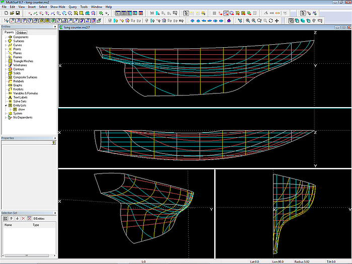
Model long_counter.ms2; the basic hull surface is trimmed against centerplane and transom.
Method 2: a surface for each purpose – canoe body, appendage
Separation of canoe body and appendage
In the models which have been presented so far hull and keel are formed by a single surface. Not any of the various concepts allows that the system of mcs simultanously defines directly both the section shape and the run of the aft overhang.
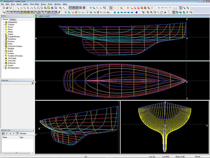
Only if the hull is separated into a canoe body and a keel appendage, the stern overhang can be directly defined and transverse mcs can be used everywhere (except for the bow mc). The model cutter-1.ms2 shows this concept.
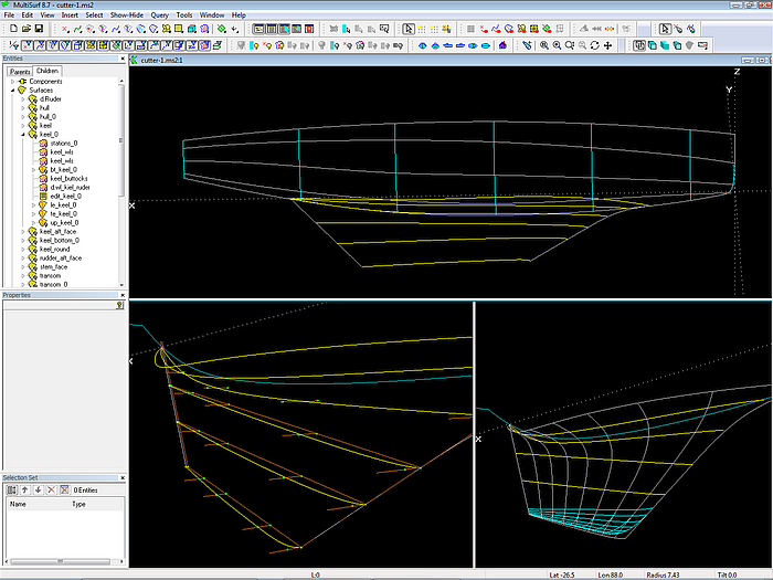
Model cutter-1.ms2: arrangement of hull mcs and keel mcs. The keel is a B-spline Lofted Surface. The rounding of the keel tip is by a Blend Surface.
The canoe body is a C-spline Lofted Surface on 7 mcs. Except the bow mc all mcs lie in transverse planes. So the shape of the mc is also the shape of the station at its x position.
The keel is a B-spline Lofted Surface supported by 6 longitudinal mcs. The first one is a snake on the canoe body, defining where the keel is attached to the canoe body. The remaining mcs in this example are B-spline Curves, each supported by 6 cps.
The rounding of the keel tip could also be done by 1 or 2 additional mcs, but in this example a Blend Surface is used for this purpose.
Note, that the cps for the keel mcs are beads on short lines normal to the centerplane, with start points on the chord lines of the mcs. This point on a line construction allows to move the control points of the B-spline Curves very easily for and aft and in and out, until you are happy with their foil shapes. Moving a chord line will move the depending curve while keeping it planar and normal to the centerplane.
B-spline Lofted Surface
A B-spline Lofted Surface is very convenient for modeling the keel of classic boats:
- The surface type is good natured: soft; it remains within the run of its mcs, easy to bend into shape, even with high curvature it does not oscillate. With a few mcs an S-shaped trailing edge of the keel can be accomplished.
- Mcs can be of different kind in spanwise direction: for example, near the root B-spline Curves with hollow tail, freeformed to match the canoe body waterlines, then further down Foil Curves, if a close resemblance to wing sections is intended.
- The rounding of keel leading edge and root can be included, no extra surfaces required.
- Enables spanwise transition of waterlines with sharp to round entry.
Model cutter-1.ms2: combination of canoe body and keel
Of course there is a price to pay:
- Only indirect relationship between mc shape and shape of contours: the B-spline Lofted Surface does not pass through its inner mcs. For example, waterlines will not coincide with mcs, even if they run horizontally. All this causes more expense in time to position control points and control curves in order to observe distinct dimensions and shape properties.
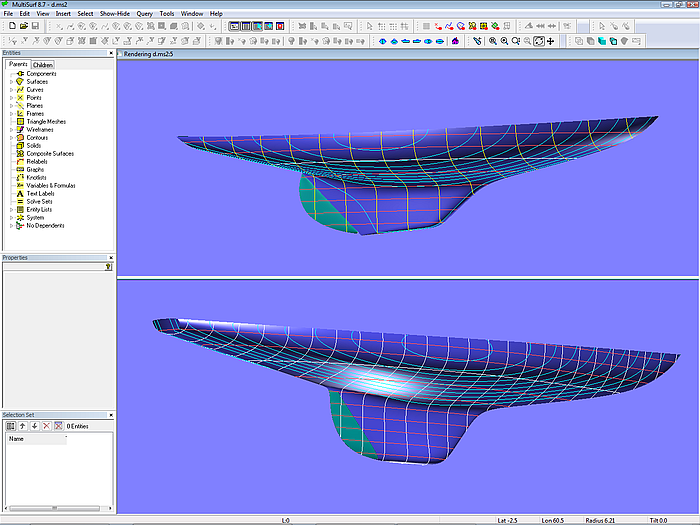
Top: Dragon (by courtesy of Klaus Roeder). Bottom: 30 square meter yacht (by courtesy of Juliane Hempel)
To summarize: splitting the hull into canoe body and keel offers these advantages:
- direct definition of the stern overhang
- use of transverse mcs – mc shape is section shape
- modification of keel shape does not affect canoe body shape
- use of stiff surface for the canoe body which is only slightly curved in fore and aft direction
- use of soft surface for the complexer shape of the keel
So far to the modeling of classic sailing yacht hulls with MultiSurf.