On the rounding of bows, sterns, sharp waterlines and
on the attachment of keels
How to make a B-spline Lofted Surface touch an other surface
by Reinhard Siegel
Introduction
There are many situations in the modeling of the geometry of hulls and superstructures, where a basis surface requires some rounding. Being small in proportion there are no sophisticated freeform requirements, except to look nice and touch adjacent surfaces smoothly.
This article shows methods how to employ the surface type B-spline Lofted Surface for a fair attachment of classic hull keels, to round the bow or the stern of a hull, to remove sharp waterline entries. Its aim is to explain the pros and cons of various procedures, so in the end you can decide which method will suit your needs best.
Abbreviations used:
cp: control point (support point)
mc: master curve = support curve
In the following the terms used for point, curve and surface types are those of MultiSurf. This may serve the understanding and traceability.
Basics
The tangential property of B-spline Curves
It is a fundamental property of the B-spline Curve, that it always starts tangent to the first segment and always ends tangent to the last segment of the polyline through its cps. This characteristic offers useful applications.
Tangency continuity. Left: two B-spline Curves join smoothly, if the common cp and its neighbours are aligned (bead e1 is on a line between points pt2 and p3). Right: tangent link of bow mc and fairbody. The previous but last cp of MC1 is a bead on the line of tangency at the start of vertex curve vl_4.
How to link two curves smoothly
We can use the tangential property to join two B-spline Curves smoothly. All what is required is, that the neigbours to the common point are in line. This relationship is easily hardwired by a simple bead-on-line construction. (Model tangent_BCurve_joint.ms2).
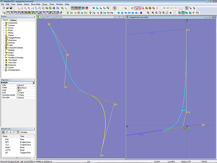
Also the link between a B-spline Curve and a curve of some other type is not difficult. For example, we can make the bow mc run smoothly into the fairbody curve by this construction: put a bead on the curve where the B-spline should touch, create the tangent in this point (line from bead to a Tangent Point based on it) and use a bead on this line as last but one control point for the B-spline Curve. (Model tangent_bow_mc.ms2).
How to make a B-spline Curve touch a surface
If the last cp of a B-spline Curve is a point on a surface (a magnet), a B-spline Curve will touch the surface in this point if its last but one cp lies on the tangent plane at the magnet. The tangent plane is defined by the normal vector at that point. (Model BCurve_tangent_at_magnet.ms2).
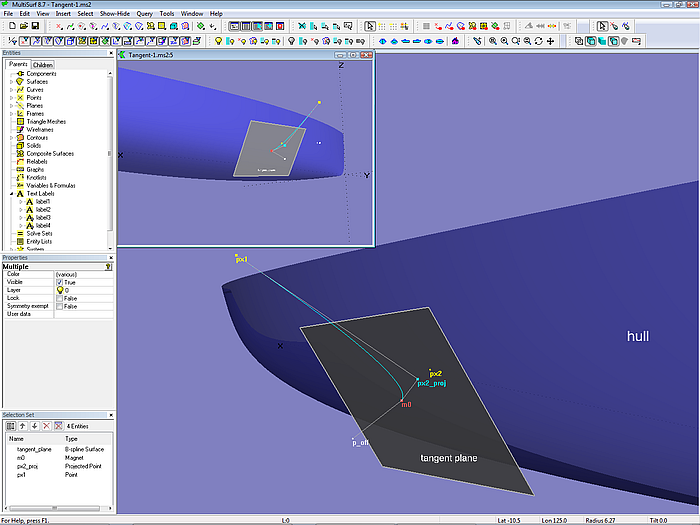
Tangency continuity (model BCurve_tangent_at_magnet.ms2): Magnet m0 is on the hull surface; tangent plane is 2 Pt Plane defined by m0 and its Offset Point p_off; last but one cp of the B-spline Curve is the projection of px2 onto the tangent plane (Projected Point px2_proj).
If the last but one cp of the B-spline Curve is a Projected Point on the tangent plane, then this tangent continuity is hardwired.
How to make a B-spline Curve touch a snake
A Snake is a curve constraint to lie on a surface, and a Ring is a point constraint to lie on a snake, thus a Ring is a point on the surface. A Tangent Point, which is based on a ring, will lie in the tangent plane at the ring. Thus, in order to make a B-spline Curve touching a snake at a ring its cp next to end must be a Tangent Point or a bead on the line of tangency. (Model BCurve_tangent_at_ring.ms2).
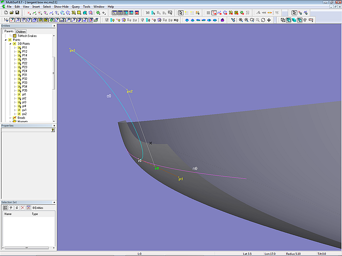
Model BCurve_tangent_at_ring.ms2: e0 is bead on tangent line at location of ring r0 on snake n0. The B-spline Curve c0 touches both snake and surface at r0.
How to make a B-spline Lofted Surface touch an other surface
As its name says, in a B-spline Lofted Surface the lofting curve is a B-spline Curve. In order to make a B-spline Lofted Surface touch an other surface one might have the opinion to use as its supports two snakes on that surface. The points on the first one defines the start, the points on the second one should ensure tangent continuity of all the lofting B-spline Curves and thus of the lofted surface itself. If both snakes are close together, the result might look not bad, but this construction does not guarantee the feature strived for. (Model non_tangent_BLoftSurf.ms2).
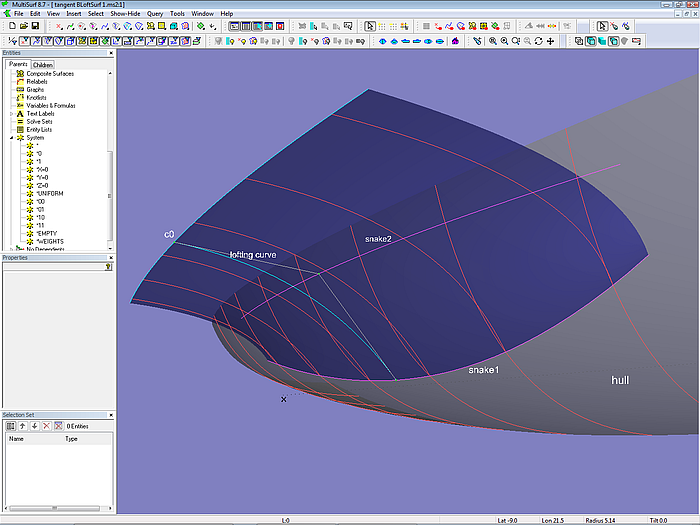
Model non_tangent_ BLoftSurf.ms2: the B-spline Lofted Surface (blue) is supported by 3 curves, the first and second one are snakes on the hull surface. Stations (red) shows tangent discontinuity.
However, it is possible to create tangency by the following construction:
- put a Ring on snake1
- create an Offset Point based on the ring
- create a 2Pt Plane based on ring and Offset Point
- copy ring on to snake2 as Copy Ring
- project the copy ring onto the plane as Projected Point
- repeat the construction of the projected point for all positions of ring as Procedural Curve
- use the procedural curve as 2nd control curve (instead snake2) for the B-spline Lofted Surface.

Model tangent_BLoftSurf.ms2: the ring on snake1 is copied to snake2, which for its part is then projected onto the tangent plane at the position of the ring. This construction is repeated for all positions of the ring by a Procedural Curve entity, replacing snake2 as support for the B-spline Lofted Surface.
Applications
We can use the foregoing explained method to model true tangential roundings, bow and stern roundings, tangential attachment of a keel, a bulbous bow and so on.
Attachment canoe body – keel
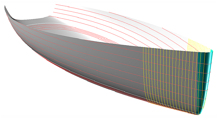
The model attached_keel.ms2 shows canoe body and keel of a traditional sailing yacht hull. The keel is a B-spline Lofted Surface defined by 6 mcs, including the turn of the garboards. The keel surface starts along snake1 on the canoe body surface, and the tangency continuity is build in as in the previous example (Procedural Curve based on snake2 and the tangent plane at the momentary location of a ring on snake1).
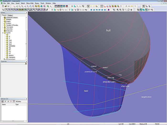
Model attached_keel.ms2: B-spline Lofted Surface keel attached to the canoe body of a classic sailing yacht hull.
How to make the Procedural Curve start on the centerplane
If both snake1 and snake2 start on centerplane and the tangent plane is not vertical here, then the start of the Procedural Curve will be a little bit away from the centerplane. This would result in a small gap along the leading edge of the B-spline Lofted Surface.
Solution 1:
Intersect the Procedural Curve with the centerplane, create a SubCurve with this intersection bead and use the SubCurve as 2nd mc for the B-spline Lofted Surface. Although by this quick fix a point on the SubCurve for a given value of t will not exactly lie on the tangent plane at a point of equal t on snake1, the deviation is very small and neglectable with regard to the accuracy one can achieve in the workshop.
Solution 2:
In a logical sense it would be better to extend snake2 a little bit forward, until the Procedural Curve starts exactly on the centerplane. This will maintain the direct correspondence between the points on the 1st mc (snake1) and the 2nd mc (Procedural Curve) of the B-spline Lofted Surface.
To extend snake2 a little bit forward put a ring is on it, which in turn supports a SubSnake. The ring for this SubSnake must be positioned to make the Procedural Curve just start at the centerplane; a small negative t-value for the ring will by typical. This search for the ring position can be done manually, but when the model is changed, it must be repeated.
However, with a Solve Set entity MultiSurf will search the correct ring location automatically. This is implemented in model attached_keel.ms2. The Solve Set ss1 contains ring1 on snake2 as the free point; bead1 is at t=0 on the Procedural Curve, and plane1 is the centerplane. The Solve Set moves ring1 along snake2 until the distance between bead1 and plane1 is smaller than the tolerance. When the model is changed the Solve Set enforces the constraint relationship.
Attachment hull – bulbous bow
Another example of the same method is model bow_bulb.ms2.
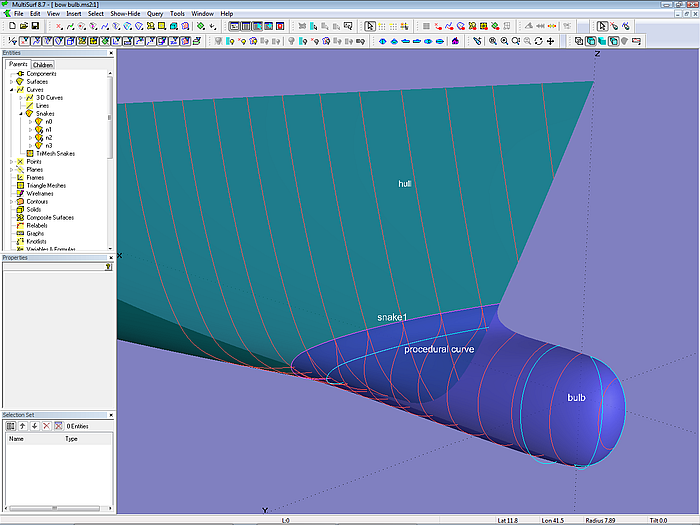
Model bow_bulb.ms2: B-spline Lofted Surface bulb attached with tangency continuity. Each point of the procedural curve is on the tangent plane at the corresponding point on snake1.
Tangential roundings
A variation of the previously shown method is demonstrated in the model classic-1.ms2. Here the bow mc of the basis hull surface has all its cps on the centerplane (bow ghost line), thus the end of the waterlines are sharp. In order to round the entry of the keel waterlines and as well as the corner between leading edge and bottom of the keel a rounding surface is added. This is a B-spline Lofted Surface on 3 supports:
- The B-spline Curve c0; it defines the wanted profile outline; it runs on centerplane first, then continues on the keel bottom surface.
- The Projected Snake n1; it is the projection of the B-spline Curve c1, which defines the end of the rounding.
- The Procedural Curve c3. It is constructed like this: a ring is placed on snake n1. At its location the tangent plane is created. The ring on snake1 is copied to the profile curve c0 as a Copy Bead, which is projected normal to the centerplane on the tangent surface as Projected Magnet. This is repeated for all positions of the ring in snake1 by a Procedural Curve.
Note, that the tangent plane is actually a surface entity. This is necessary, because the projection direction is not normal to the tangent plane, but normal to the centerplane of the boat hull. With a 2 Pt Plane the direction of projection cannot be different to the normal vector of the plane itself.
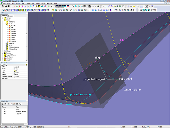
Model cutter-1.ms2: tangential rounding of leading edge and bottom of keel by B-spline Lofted Surface. Ring is located on snake n1, which defines the end of the rounding on the hull surface. B-spline Curve c0 defines the keel profile.
Bow rounding – nearly tangential
Suppose we have a basis hull surface where the bow mc is the half siding of the stem. Then we will get a bow rounding B-spline Lofted Surface supported by
- snake n_start, which defines the begin of the rounding on the hull surface
- mc1, the bow mc of the basis hull surface
- mc1_proj, the projection of mc1 on the centerplane (Projected Curve)
This cheap construction is demonstrated in model sailboat_bowround.ms2. As long as the hull surface is more or less flat lengthwise, there is nearly tangent continuity between the two surfaces. Sailboat hulls tend in this direction, but with powerboats and their full topside waterlines a break in slope will be noticeable.
Side step
It is very convenient, if the bow mc defines the half siding of the stem. Then the shape of the stem in profile view is determined directly by the x an z coordinates of the cps, the y coordinates of the cps define the bluntness of the stem. If the bow mc is the stem ghost curve on the centerplane, then there is just an indirect relation. If the actual stem in profile is fine, but its face is too small or wide, the shape of the foreship must be edited to make the waterlines wider or finer. In the author´s opinion a direct control of the prominent curves of a design is very important.
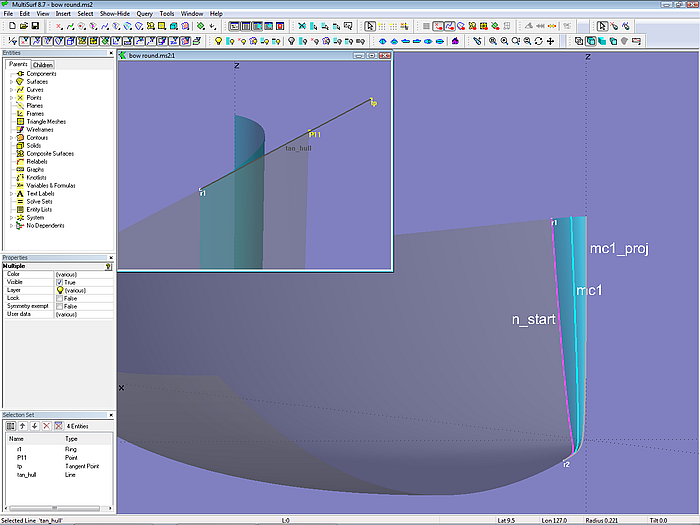
Model sailboat_bowround.ms2: the B-spline Lofted Surface is controled by a snake on the hull, the bow mc of the hull and its projection onto the centerplane. Cheap and simple, but not necessarily truly tangential.
However, this simple bowround construction fails when used with a hull surface that is visibly curved in the fore-and-aft direction. This is shown in model bad_bowround.ms2 for the rounding of a bulwark basis surface. There is a considerable deviation between the tangent line to the top edge of the bulwark at point r1 and the line r1 to p11, to which the top edge of the bow round surface is tangent.
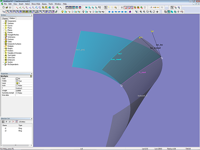
Model bad_bowround.ms2: The simple bowround construction fails when used with a surface that is curved in fore-and-aft direction. The discrepancy between the tangent line to the top edge of the bulwark at point r1 and the line r1 to p11, to which the top edge of the bow round is tangent, is noticeable.(Looking forward).
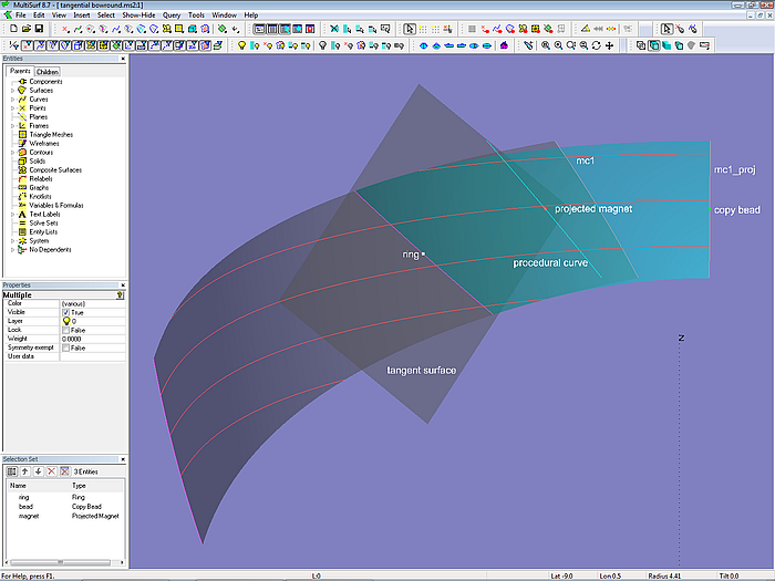
Bow rounding – true tangential
However, it is possible to create tangency by the following construction:
- put a ring on snake n_start (the snake where the rounding starts)
- create a tangent surface at ring
- copy the ring to mc1_proj as Copy Bead
- project the copy bead onto the tangent surface as Projected Magnet
- repeat the construction of the projected magnet for all positions of the ring as Procedural Curve
- use the procedural curve as 2nd control curve (instead mc1) for the rounding B-spline Lofted Surface.
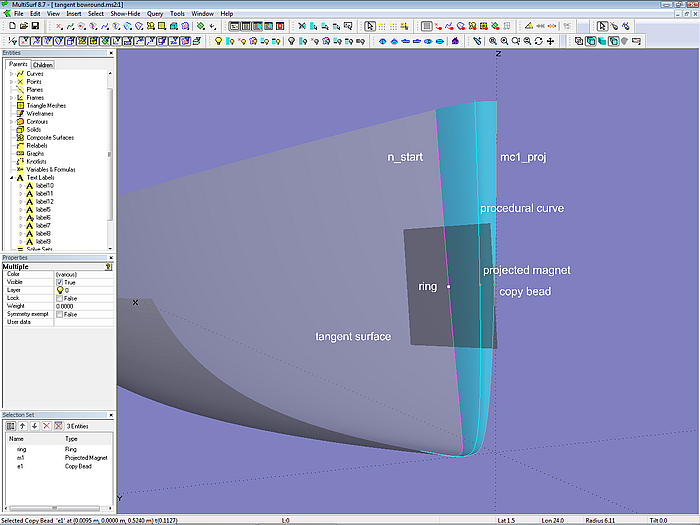
Along this lines the slope discontinuity of the imperfect bow round is fixed in the model good_bow-round.ms2.
Model good_bowround.ms2 (looking aft). Tangency continuity by using a procedural curve instead of mc1.
This approach is also shown for the sailboat hull in the model angential_bowround.ms2.
Model tangential_bowround.ms2
Bowround by Blend Surface
Among the MultiSurf Examples there is the model Bowround2.ms2 where the rounding of a bow is accomplished by the surface type Blend Surface. For the sailboat hull above this method is pointed out in the model bowround_blend.ms2:
- project mc1 onto the centerplane (mc1_proj)
- span a Ruled Surface between mc1 and this projected curve (stem face)
- create both its outer and inner edge snakes (sn_3, sn_4)
- create the edge snake along the bow of the hull (sn_2; it is on top of sn_3)
- create the snake where the rounding starts (n_start)
- create the Blend Surface using these four snakes.
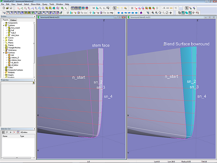
Model bowround_blend.ms2: the corner between hull and stem face is rounded by a Blend Surface.
The Blend Surface property “Type” controls the smoothness of the join between the Blend Surface and the basis surfaces: Type = 1: slope continuity; Type = 2: curvature continuity.
However, as the comparison between the tangential bow rounding and those with the Blend Surface type 1 or type 2 reveals, the shape of the waterlines is not in favour for the latter. The Blend Surface bowround with curvature continuity shows even blunt waterlines (due to the flatness of the stem face).
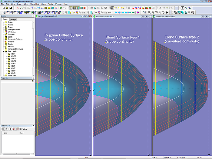
Comparison of bow roundings by B-spline Lofted Surface and Blend Surface
Stern rounding
The construction of a stern rounding follows the same principle as described for the true tangential bow round. (Model stern_round.ms2).
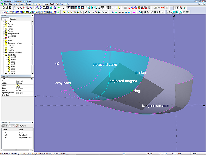
Model stern_round.ms2: application of the true tangential B-spline Lofted Surface method
Work-around in case the projection fails
The construction of bow and stern rounding by a touching B-spline Lofted Surface is based on the procedural curve, which repeats these 3 steps for all positions of a ring on the snake which defines the start of the rounding:
- at the position of the ring create the tangent surface,
- copy the ring to the profile curve on the centerplane
- project normal to the centerplane the resulting copy bead onto the tangent surface as projected magnet
In case there is a failure due to a too small angle between the line of the projection and the surface the magnet is to lie on, then this is the work-around:
- put a ring on the start snake, say, at t = 0.9 (try the greatest value until the error occurs)
- copy the ring to the profile curve c0
- make a SubSnake on the start snake with the ring and a SubCurve on c0 with the copy bead
- replace both start snake and profile curve by this children
The result will be a stern round, which is open at its bottom end. The longer the SubSnake and the SubCurve the smaller the hole. Close the hole by a Tangent Boundary Surface, a kind of surface, which allows to impose tangency and curvature continuity conditions along its boundary edges.
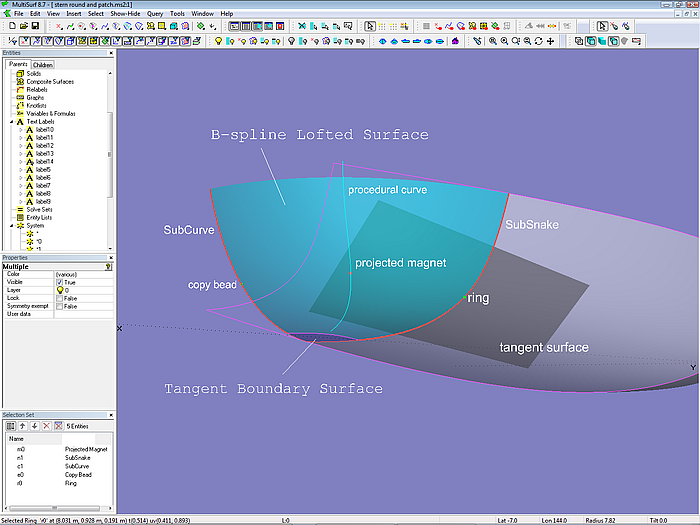
Model stern_round_and_patch.ms2: In case the projected magnet is in error because the line of projection and the tangent surface are parallel, exclude the problematic area by using a portion of the start snake (SubSnake) and a portion of the profile curve (SubCurve). The gap is filled conveniently by a Tangent Boundary Surface.
So far to the modeling of a B-spline Lofted Surface to make it touch an other surface.