Modeling the Hull Measurement Rules of Square Metre Yachts by Variables and Formulas
by Reinhard Siegel
Introduction
The design of a yacht in accordance with specific class regulations requires the permanent comparison of hull dimensions against rule measurements. The function "Distance" provides a dynamic display of the distance between two points (also arc length distance, in case the points lie on the same curve/snake). A series of distance reports can easily be created to show hull particulars. However, distance reports are not persistent between MultiSurf sessions (also are not included in Undo/Redo sequences). Often class rules require some further mathematical operations of measured values Thus the application of variables and formulas is a more powerful way to produce class rule measurements for use in the design process.
The implementation of a measurement rule in a MultiSurf model is shown by means of the rules for the square metre yachts (skerry cruisers).
Abbreviations used:
cp: control point (support point)
mc: master curve = support curve
Rules for square metre yachts
Basis for the hull regulations is a table of hull particulars of an ideal square metre yacht. If certain measurements exceed the ideal ones, displacement, mean breadth, freeboard and length of keel are to be increased.
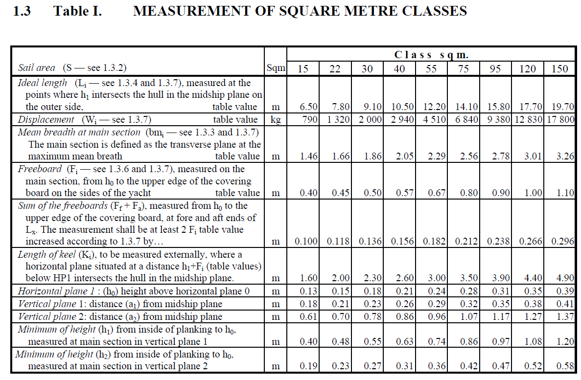
Table I: ideal hull particulars (taken from "Rules for skerry cruisers (square metre yachts)", SSKF, 2013)
Measurements are taken at a variety of horizontal and transverse sections.
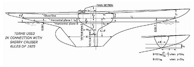
Definition of horizontal and transverse measurement sections (taken from "Rules for skerry cruisers (square metre yachts)", SSKF, 2013)
Example: 15 square metre yacht
As an example we will consider the hull model of a 15 square metre yacht (sk15-1.ms2). By no means it is intended to create a complete model with deck, transom, rudder and so on. It is also not about a hull shape of specific proportions except that it fits to the class rules.
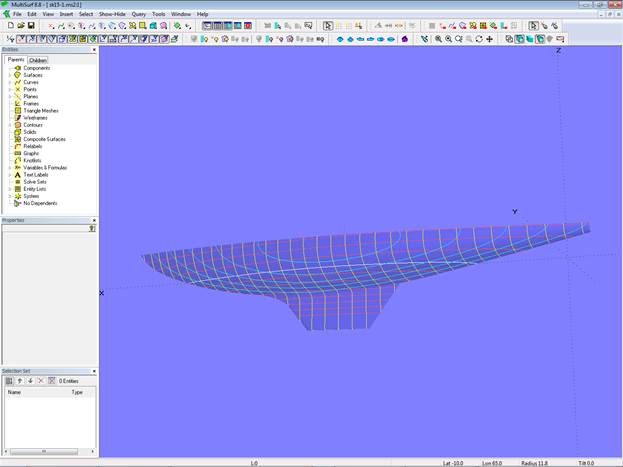
Modell sk15-1.ms2
The boat is composed of 3 surfaces: the C-spline Lofted Surface "hull_0" (canoe body), the B-spline Lofted Surface "keel_0" (basis keel) and the Blend Surf "keel_fillet" (transition from canoe body into keel).
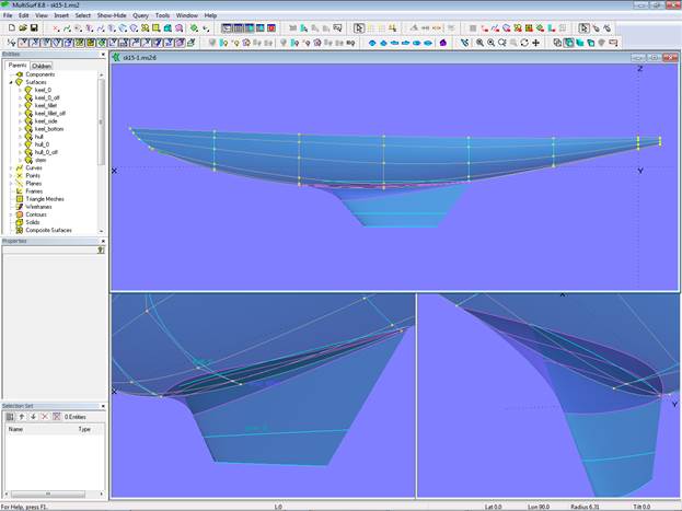
Canoe body, keel basis and fillet
The canoe body is defined by 8 mcs, each a B-spline Curve of degree 3 with 6 cps. Vertex curves (C-spline Curves which connect corresponding cps) serve as guides for fairing. The keel basis is supported by 3 B-splines with 6 cps each, running in waterline direction. The keel fillet is supported by B-spline Snakes, each controled by 6 magnets.
There are several Entity Lists. Select one, then use "Show Parents" to display their members The list "edit_hull 0" holds all entities for shaping the hull.
The list "measurements" contains the measurement data. Its display is by Text Labels. The group "Table Values" holds the data according to Table I. The table values are implemented by Variables.
The group "Measured Values" lists the result of measurements at the various locations. Formulas are used for calculation.
The group "Required Values" shows the increased dimensions if length exceeds the ideal length Li.
There are also separate entity lists for these data, defined by variables or derived from formulas. This allows their display via Tools/ Real Values or the shortcut key "V" in separate windows.
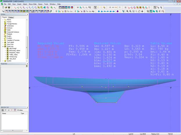
Measurement data and defining sections
When hull or keel is edited, the effect on the measurement values is immediately shown.
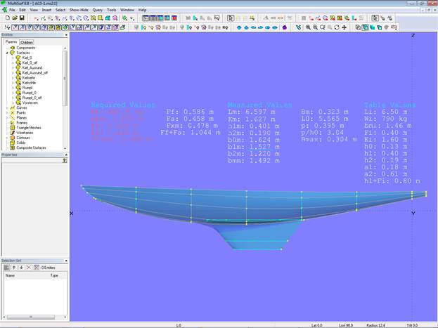
Measurement data and hull and keel mastercurves
Formulas used
The formulas used here are simple ones. Some do mathematical operations, but most report the XYZ location of a point or the distance between two points.
The formula functions XPOS, YPOS, ZPOS, TPOS return the XYZ and t position of a point. For example, ring10 is at the top of the main section; then the freeboard is calculated by the formula Fxm, which uses the expression: ZPOS(ring10).
Another example: the points ring11 and ring12 are at start and end of the waterline. Then the waterline length is calculated by the formula L0, using the expression: XPOS(ring11)-XPOS(ring12).
The user documentation lists all functions available for use in formulas, for example ARCLEN (girth length between two curve points), AREA (area of a surface), CENTROID (XYZ coordinates of center of area).
Main section
The determination of the main section deserves a closer look. The main section is defined as the transverse plane at the maximum mean breadth bmm. The definition of mean breadth is: bm = (b0 + 4 x b1 + b2) / 6; b0, b1, b2 are breadth measurements: b0 at the sheer, b1 at plane1 and b2 a certain distance below plane1. The main section is the one where bm is at maximum.
In order to automate this search for the maximum mean breadth the Bead e0 is created on Line l0 on the centerplane. At the X-position of e0 those 3 breadth measurements are taken by the help of XYZ Rings. Then bm is calculated by the Formula bm_i. This value is used for the Z-position of Point pt15.
Now the t-position of e0 is changed from 0 to 1 and the path of pt15 recorded via the Procedural Curve c0. The maximum Z elevation of this curve is found by the Proximity Bead e1. Its X-position is the wanted location of the main section.
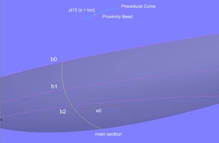
Determination of main section by procedural construction
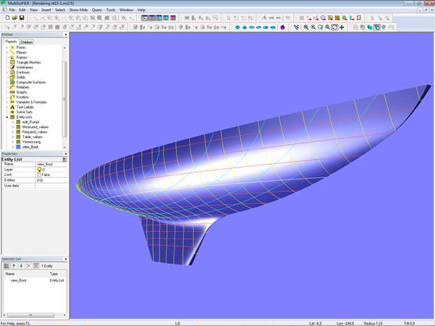
15 sqm yacht hull
So far to this.