Bowrounds - update 2018
On Methods How to Construct a Tangent Bowround Surface
by Reinhard Siegel
Almost Tangential Bowround
Model bowround-1.ms2 shows the simplest construction of a bowrounding, a B-spline Lofted Surface with three support curves – a snake on the hull surface, where the bowround starts, the first hull mastercurve and its projection onto the centerplane.
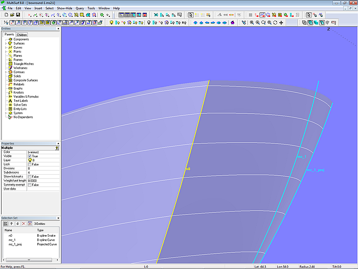
Model bowround-1.ms2 – B-spline Lofted Surface, simple, but without hardwired tangency
This construction is simple and program response is fast, but it has the disadvantage that no tangential joint to the hull surface is ensured. For surfaces that are only slightly curved in the longitudinal direction, this can hardly be seen in the waterlines, but with hulls that are more curved in the bow area, breaks can be seen clearly.
Only a smooth contact of the bowrounding by firm construction of the model can provide remedy.
True tangent bowrounds
There are several ways to incorporate the tangential joining of bowround and hull in the model.
Procedural Surface< - update 2018
The model bowround-2.ms2, which was presented at the 2017 workshop, showed a disadvantage: its evaluation time is considerable, about 10.8 seconds on a standard computer. This causes forced breaks when editing the hull geometry.
In the 2017 model the tangent line between ring3 and the Tangent Point to pt1 was intersected by the stem face help surface in the Intersection Bead e1, which was then projected onto the centerplane (Projected Point pt2). Thus the moving curve of the Procedural Surface, the B-spline Curve curve1, was defined by ring3, e1 and pt2.
A considerable improvement in execution speed is achieved, if the tangent line intersects the stem help surface, and not the stem help surface intersects the line.
The evaluation time of the Procedural Surface is now 0.2 seconds.
So here is the description of the updated construction of the model bowround-2.ms2.
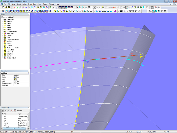
Model bowround-2.ms2 –by procedural construction built-in true tangency of bowround and hull surface
On the snake, which defines the entry of the bowround surface, the Ring ring3 is located as parent of a longitudinal UVSnake. The tangent at the position of ring3 is then created on this snake by means of the Tangent Point pt1. The line from ring3 to pt1 intersects the stem face help surface (being perpendicular to the centerplane) in the Intersection Magnet m1. This intersection magnet is then projected onto the centerplane as Projected Point pt2. The points ring3, m1 and pt2 are now parents of the B-spline Curve curve1. Finally, the construction of this curve is repeated by a Procedural Surface for all positions of ring3. That is, moving curve of the Procedural Surface is curve1, drinving point is ring3.
Advantage of this method is the true tangential link of bowround and hull surface.
Note:
It is important that the tangent line intersects the stem face help surface (Intersection Magnet m1). Why not cut the line by the help surface in an Intersection Bead and use that one as parent for pt2 and curve1? In theory this is possible, but in practice it is not a feasible idea as the evaluation time of the bowround will be increased considerably.
B-spline Lofted Surface with C-spline Mc
Model bowround-3.ms2 shows an approach that does not require procedural entities. However, only an approximate tangential joint can be achieved, but the results are considerably better than with a standard bowround according to model bowround-1.ms2.
On the B-spline Snake, which specifies the beginning of the bowround surface, several rings are created; these are parents of Relative Magnets with du = 0. Each ring and associated magnet determine a Line Snake plus the tangent at its front end - much like the previous model bowround-2.ms2. These tangents to the hull surface are cut by the stem help surface in Intersection Beads. A C-spline Curve interpolates these beads.
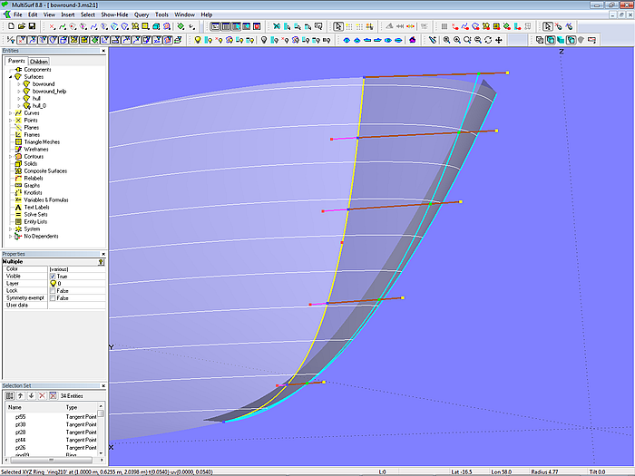
Model bowround-3.ms2 - a C-spline Curve interpolates the intersections of a series of hull tangents with a help surface. After relabeling by a SubCurve it is used as the 2nd mc of the B-spline Lofted Surface bowround.
Since the parameter distribution of the B-spline Snake is very different from the C-spline Curve, it is relabeled with the aid of a SubCurve in order to make the u-constant parameter curves of the bowround running approximately parallel to the tangent lines.
As said, this approach is not perfect, but fast. It gives better results than the standard construction model bowround-1.ms2.
B-spline Lofted Surface with Procedural Curve
Model bowround-4.ms2 shows an alternative to the previous models. First, at the position of the Ring ring3 on the snake n0 (beginning of the bowround) the tangent plane to the hull surface is generated using an Offset Point. Next the 1st mc of the hull surface is projected onto the centerplane (Projected Curve mc1_proj). Now ring3 is copied onto it as Copy Bead e1. This bead is then projected onto the tangent plane as Projected Magnet m1, perpendicular to the centerplane. The construction of this Projected Magnet is repeated for all positions of ring3 as Procedural Curve c1. Snake n0, Procedural Curve c1 and Projected Curve mc1_proj are now the parent curves of the B-spline Lofted Surface bowround.

Bowround-4.ms2 - the inner control curve of the B-spline Lofted Surface bowround is a procedural curve with points that lay on tangential planes of the hull surface.
Please note, that the tangent plane is not a Plane entity, but a planar B-spline Surface.
This construction ensure true tangency. Also the program responses fast to changes.
Tangent Boundary Surface
How about using a Tangent Boundary Surface for the bowround? A Tangent Boundary Surface is bounded by four curves. A point can also serve as a curve (i.e. all curve points are identical). The Tangent Boundary Surface supports end conditions - if a curve is a snake, the surface starts tangent to the host surface of the snake. Further, this surface kind offers interior control points for fine tuning the interior form of the surface. In model bowround_tbs.ms2 this method is demonstrated.
The parents of the Tangent Boundary Surface are curve1, c0, ring2 and n0. Curve1 is a B-spline Curve at the top of the bowround; it starts tangent to ring1 on the sheer edge of the hull and ends normal to the centerplane. C0 is the projection of mc_1 of the hull onto the centerplane. Ring2 is located at the t = 1 end of snake n0 on the hull, where the bowround starts.
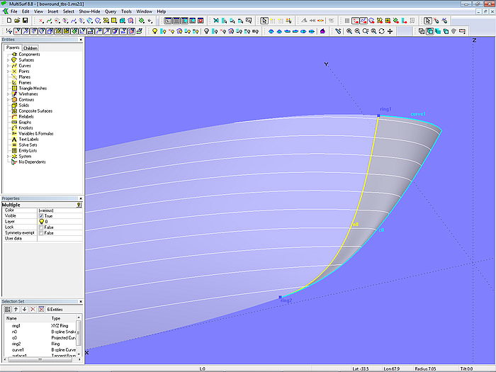
Model bowround_tbs-1.ms2 –bowround by Tangent Boundary Surface
Continuity along edge 2 (Projected Curve c0) is “slope” – because c0 is a Projected Curve, the continuity “slope” makes sure, that the Tangent Boundary Surface ends normal to the surface/plane, onto which c0 is projected (*Y = 0). Continuity along edge 4 (snake n0) is also “slope”, so there is a tangent joint between bowround and hull.
The initial shape of the Tangent Boundary Surface shows, that the waterlines start normal to CL and end tangent to the hull, but are too blunt near the forefoot.
The number of u-control values is then set to a minimum of 3; this results in a single free interior control point, which must be visually positioned to achieve a fair run of the waterlines (model bowround_tbs-2.ms2).
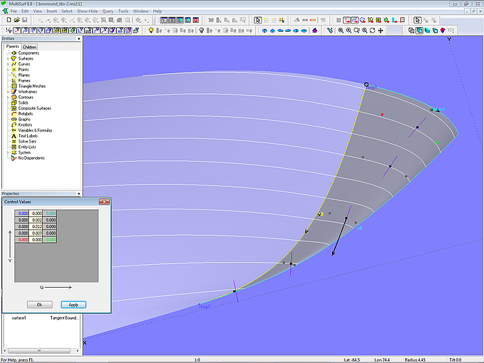
Model bowround_tbs-2.ms2 - waterlines faired by moving interior control points of the Tangent Boundary Surface.
Although the edge continuity hardwires that the Tangent Boundary Surface is truly tangent to the hull surface and normal to the centerplane, there is no built-in guarantee that waterlines are automatically fair. Between the tangent start and the normal end there are many possible shapes. Without editing of interior control ponts a satisfying form will not be achieved.
In the author´s opinion there is too much fiddling, too much manual fairing work required, although the construction of a bowround by the Tangent Boundary Surface needs just a few entities.
So far to the bowround topic.
======================================================================================