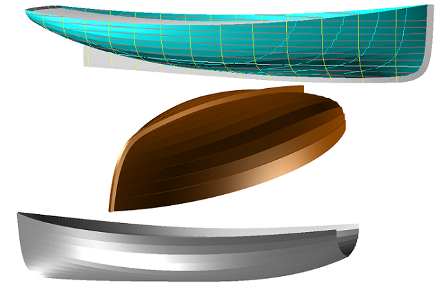
Hull with Clinker Planking
Two Modeling Methods
by Reinhard Siegel
July 2025
Content
Introduction
1 Clinker Planking – Principle
2 Workboat with Clinker Planking
2.1 Base Hull
2.2 Planking Layout
2.3 Plank Cross-sections
2.4 Planks
2.5 Hull Surface in Clinker Shape
2.6 Plank Expansion
3 Workboat with Clinker Planking – Advanced
3.1 Variables for Plank Thickness and Landing
3.2 Formulas for Plank Width
4 Clinker-skin Method
5 Examples
5.1 Dinghy (plank cross-section method)
5.2 Sailboat (clinker-skin method)
Appendix 1 – Surface Model Based on Diagonal Section Offsets
Appendix 2 – Graphical Representation of Plank Width
Introduction
The hull of a wooden boat can be constructed using various methods. There is the batten construction, the construction from molded veneer or plywood strips, the classic carvel construction, and the clinker construction. In clinker construction, the planks overlap like roof tiles. Viking ships were built using this method. The folkboat is also a well-known example.
This tutorial will first demonstrate how to model a clinker hull using the example of a workboat. The procedure will be extended through the use of variables and formulas. A method will then be presented for creating a hull surface that merely resembles a clinker construction (GRP boat). Two more examples of clinker boats conclude the tutorial.
Abbreviations used:
cp: control point (support point)
mc: master curve = support curve
cp1, cp2, ...: denotes 1st, 2nd, ... point in the list of supports of a curve. It is not an actual entity name.
mc1, mc2, ...: denotes 1st, 2nd, ... curve in the list of supports of a surface. It is not an actual entity name.
In the following the terms used for point, curve and surface types are those of MultiSurf. This may serve the understanding and traceability.
1 Clinker Planking – Principle
If we model a boat hull in MultiSurf that is to be built using the carvel construction method, we generally do not need to worry about the individual planks. It is sufficient to create the lines for a hull surface that has the desired shape. Dividing the surface into planks would then be a task during the actual building of the boat. However, if desired for work preparation purposes, this can also be done in MultiSurf. See:75 sqm Yacht – from screen to sea
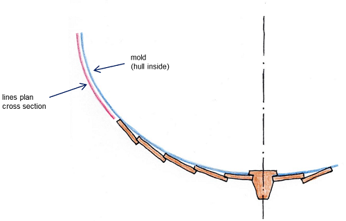
If, on the other hand, we want to model a boat hull with clinker planking, we have to create each individual plank. This requires a correspondingly large amount of effort. The structure of the model corresponds to the procedure in practice. The starting point is a round-bilged hull geometry. This base surface is offset inward by the plank thickness (offset surface). It is intersected by a series of transverse stations, the molds. Together with the stem and stern, these molds form the supporting curves of the planks.
Due to the overlapping of the planks, we must start with the lowest plank. Its inner side runs with its lower edge in the rabbet of the stem and keel, and its upper edge lies on the offset surface. For all subsequent planks, the inner lower edge runs on the outer side of the previous plank, and its inner upper edge lies on the offset surface.
Clinker hull construction – overlapping planks
The mold in the middle of the hull is divided according to the number and width of the planks. The other molds receive the same relative division. Connecting corresponding division points creates longitudinal curves for the upper edges of the planks' inner sides. These curves are referred to below as plank seams.
Viewed from all directions, these curves should be fair and look nice. Their distance from one another should change evenly. Because the edges of the planks are clearly visible due to their overlap, the plank seams fundamentally determine the appearance of the clinker hull.
The plank seams should run fair and look nice (here, some more work is advisable).
At the stem, the planks are notched in the landing region so that they can run into the rabbet without overlapping. Optionally this can also be done at the plank ends at the stern.
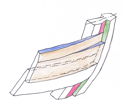
Entry of the clinker planks into the rabbet of the stem
How to model a clinker-built hull in MultiSurf will be shown in the following using the example of a workboat. First, the plank pattern for the round-bilged base hull is created, then inside and outside of the planks are defined.
2 Workboat with Clinker Planking
2.1 Base Hull
The chosen example is based on measurements for a workboat given in the text-book Bootsbau und Holzschiffbau (J. Börms; Hamburg: Verlag Handwerk und Technik, 1960).
Appendix 1 in this tutorial, Surface Model Based on Diagonal Section Offsets, shows the procedure for creating a hull surface from diagonal section offsets. The result is model clinker-0.ms2 with the C-spline Lofted Surface base_hull.
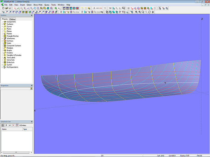
Model clinker-0.ms2 – base hull of the workboat (C-spline Lofted Surface base_hull)
Since in what follows only the hull surface is required from model clinker-0.ms2, contours of stations, waterlines, etc. are deleted and the model is saved under the file name clinker-1.ms2.
2.2 Planking Layout
To create the hull, the number of planks must be determined. Given the intended use and the size of the boat chosen here, a total of 10 planks per hull side is assumed. The thickness of the planks should be 0.010 m, and the overlap of the planks should be 1.7 times the thickness (0.017 m).
Molds
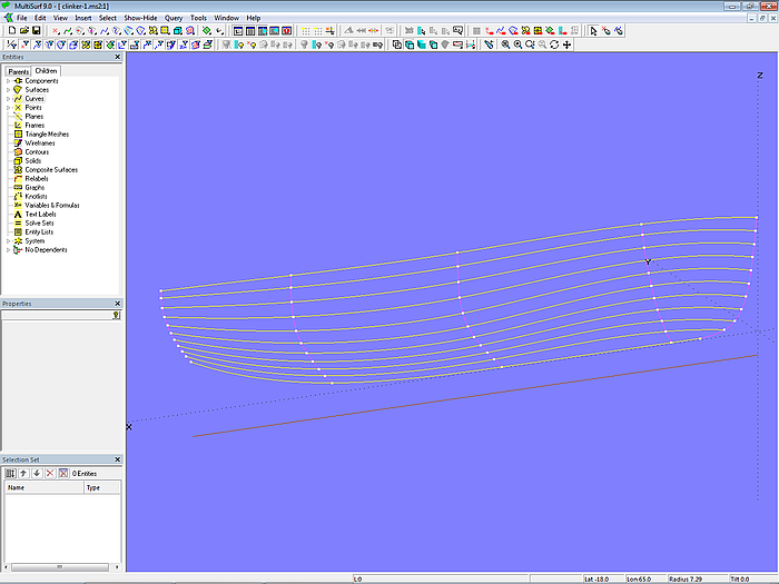
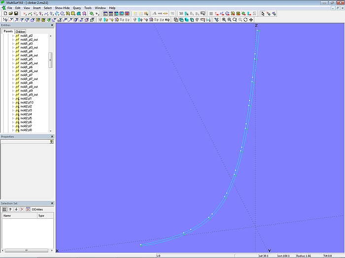
Now the plank layout must be defined. With 10 planks, we get 9 plank seams. First, the Offset Surface base_hull_off is created, offset inward from the base hull by the plank thickness. EdgeSnake mold_1 runs along the leading edge of base_hull_off as the inner edge of the stem rabbet. EdgeSnake mold_5 runs along the trailing edge. Together, both are the outer molds. Now, on Line baseline the three XYZ Beads x_mold_2, x_mold_3, and x_mold_4 are placed. They determine the position of the inner molds mold_2, mold_3, and mold_4, which are created by transverse Intersection Snakes. These Snakes also lie on the Offset Surface base_hull_off.
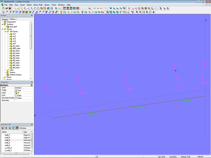
Model clinker-1.ms2 – molds for dividing the hull surface into planks
Mold points – equal spacing
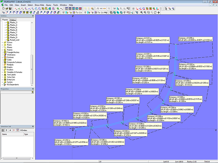
Now we need points on the molds through which the plank seams should run. Let us assume that the planks should have the same width at each mold. Then the arc length (girth measurement) of the mold must be divided into 10 equal parts.
To do this, first place Rings at the beginning (t = 0) (m1_r0, m2_r0, ... m5_r0) and at the end (t = 1) (m1_r10, m2_r10, ... m5_r10) of each mold. If you select a matching pair, you can display the arc-length using Tools/ Measure/ Distance (or the corresponding button in the Toolbar). For example, for mold 3 the arc-lenght is 1.2918 m and for mold 4 it is 1.1937 m.
Model clinker-1.ms2 – display of girth measurement for molds 3 and 4 via Tools/ Measure/ Distance
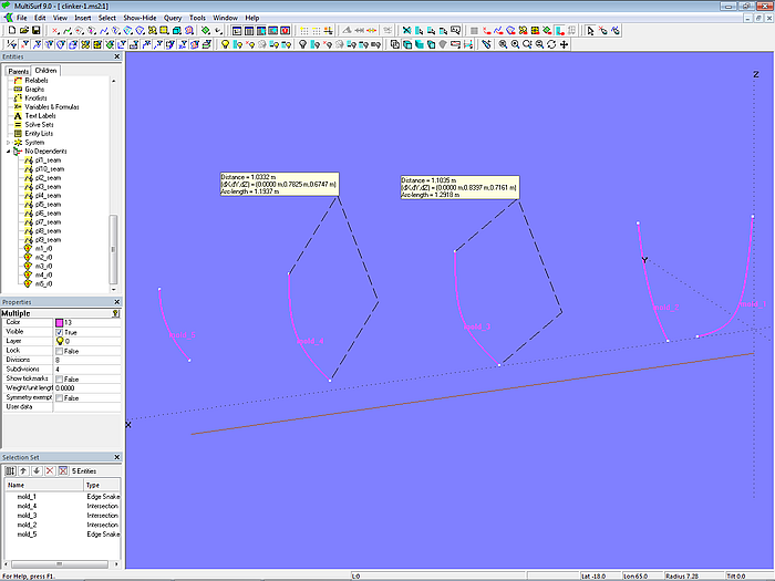
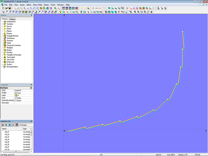
This means, for example, we need to set 9 points on the Intersection Snake mold_3. For this we use the Point type Arc-length Ring. The result are the Arc-length Rings m3_r1, m3_r2 ... m3_r9. The points m3_r2, m3_r3 ... m3_r9 are each separated by 0.1292 m.
However, to the first point m3_r1 the landing must be added; the distance from m3_r0 is then 0.1462 (0.1292 + 0.0170).
Model clinker-1.ms2 – display of the girth measurement for mold 3 and the distance between mold points
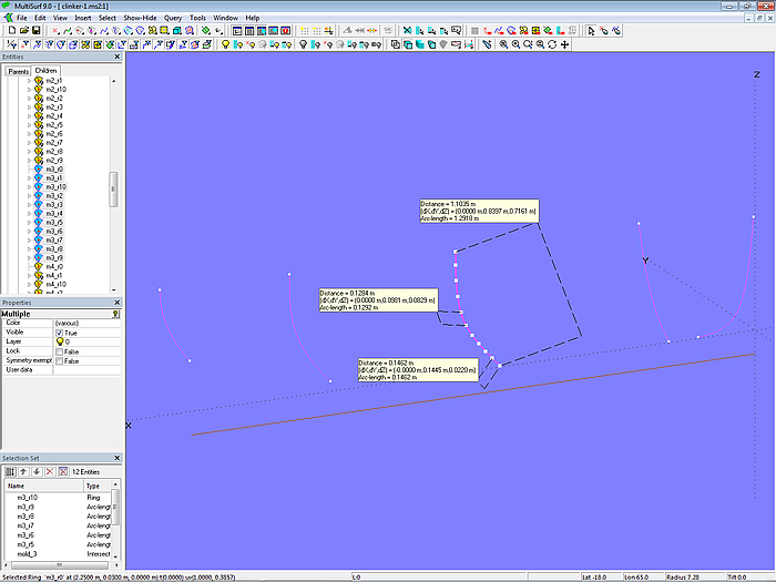
In a similar way the inner mold points on the other molds are created (m1_r1, m1_r2 ... m1_r9; m2_r1, m2_r2 ... m2_r9; m4_r1, m4_r2 ... m4_r9; m5_r1, m5_r2 ... m5_r9).
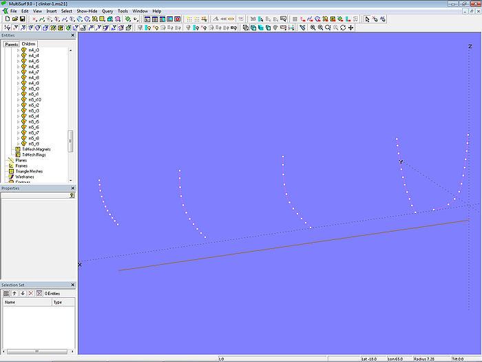
Model clinker-1.ms2 – Arc-length Rings as mold points divide the girth of the molds into 10 equal parts.
Plank seams
Corresponding mold points are now connected by the C-spline Curves pl0_seam to pl10_seam.
The model is then saved under the file name clinker-1.ms2.

Model clinker-1.ms2 – C-spline Curves interpolate corresponding mold points to form plank seams.
The plank seam curves have no dependent objects. They are only used to indicate whether the plank widths change evenly longitudinally and whether the plank run looks good. In other words, whether the mold points on the molds are harmoniously arranged. For example, in the bow area, the lower seams show an inflection point in side view. This can be corrected by moving the points on mold_1 and mold_2 accordingly. However, care must be taken to ensure that the spacing of the mold points along a mold curve does not change irregularly.
Graphical representation of plank widths
In model clinker-1_final.ms2, an attempt is made to reduce the S-shape of the plank seams somewhat by moving the points on mold 1 and mold 2. This can be done by eye, with the run of the seams viewed from different directions.
Here a graphical representation can be helpful which shows how the plank width changes over the mold length. Appendix 2 of this tutorial describes how to construct such a diagram. It can be inserted into the model via File/ Component/ Load as Component diagram_10planks.mc2.
Model clinker-1_final.ms2 includes diagrams for mold 1, mold 2, and mold 4. The positions of the Arc-length Rings for the mold points can also be changed using the keyboard. Select a point on the mold so that its properties are displayed in the Properties Manager. Then click in the right part of the field "Arc dist"; now you can change the arc-length using Alt+Up Arrow/ Down Arrow. At the same time, the diagram display updates.
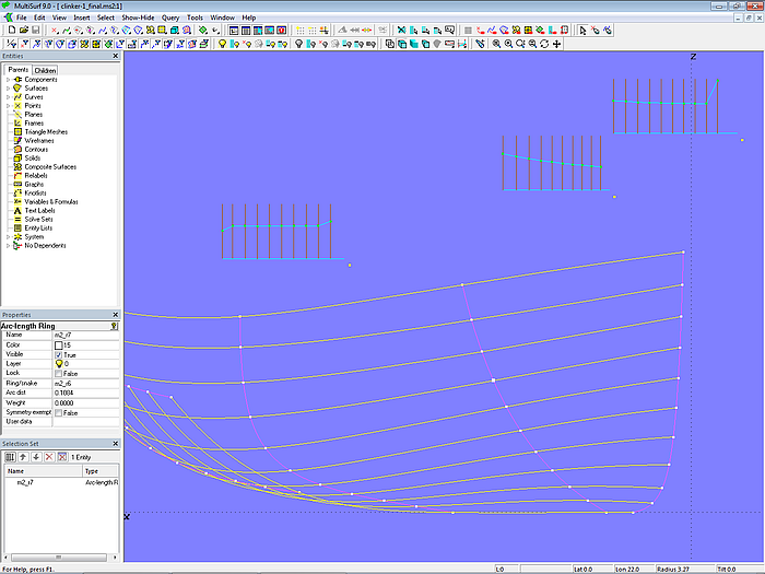
Model clinker-1_final.ms2 – fairing the plank seams using plank width diagrams
2.3 Plank Cross-sections
Now, let us save the model clinker-1_final.ms2 under the file name clinker-2.ms2. In the following we add the plank cross-sections to the individual molds.
Mold 3
We start with mold 3 and create the plank cross-sections there. With corresponding cross-sections at the other molds, they serve as master curves for the actual planks.
Plank 1 - Cross-section
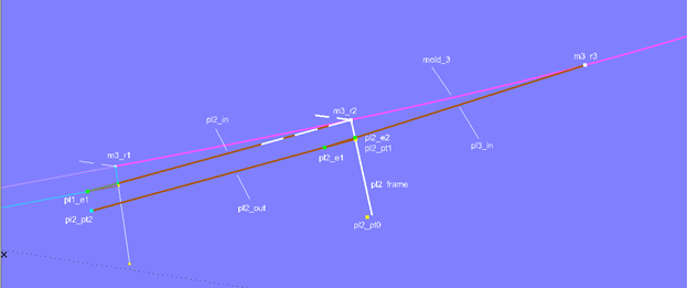
Due to the plank overlap, we begin with the bottommost plank (plank 1). Its cross-section lies with its inner line on Offset Surface base_hull_off. Spanned between the first mold point (Arc-length Ring m3_r1) and the beginning of mold 3 (Ring m3_r0), it is represented by Line pl1_in.
Now, the Offset Point pl1_pt0 is created relative to m3_r1. The 3-point Frame pl1_frame is then defined with m3_r1 (end of inner line), m3_r0 (beginning of inner line), and pl1_pt0. At the distance of the plank thickness (0.010 m) from the origin in X-direction of this frame Point pl1_pt1 is located. Using pl1_pt1, m3_r1, and m3_r0, the Copy Point pl1_pt2 is defined.
The outer line of plank 1 is Line pl1_out, which connects pl1_pt1 and pl1_pt2. On Line pl1_out the Arc-length Bead pl1_e1 is located at the distance of the landing width (0.017 m).
To create the bevel of the overlap between plank 1 and plank 2, the second mold point (Arc-length Ring m3_r2) is connected to pl1_e1 by Line pl2_in. This line is intersected by the XY-plane of Frame pl1_frame in the Intersection Bead pl1_e2.
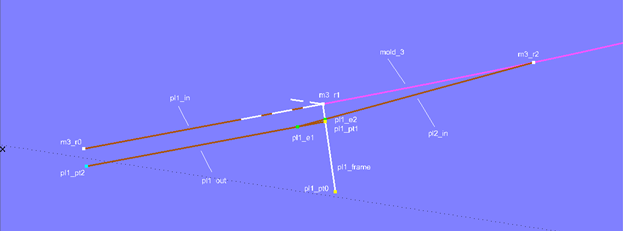
Model clinker-2.ms2 – constructing the vertices of plank 1 at mold 3
This completes the creation of all five vertices of plank 1, and they can be connected to the plank cross-section using the B-spline Curve pl1 (degree = 1).
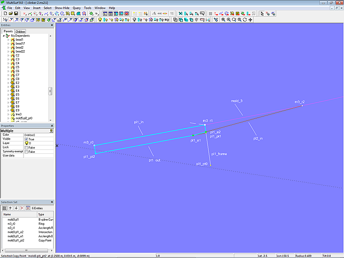
Model clinker-2.ms2 – cross-section of plank 1 at mold 3
Plank 2 – Cross-section
The cross-section for plank 2 is built in a similar way.
Model clinker-2.ms2 –construction of the vertices of plank 2 at mold 3
Model clinker-2.ms2 – cross-section of plank 2 at mold 3
Plank 3 – Plank 9: Cross-sections
The cross-sections for planks 3 to 9 at mold 3 are created accordingly.
Plank 10 – Cross-section
The modeling of the cross-section of plank 10 is simple compared to that of the other planks.
Model clinker-2.ms2 – cross-section of plank 10 at mold 3
Therewith all plank cross-sections of mold 3 are defined.
Model clinker-2.ms2 – plank cross-sections at mold 3
Let us now check how the plank layout looks from the outside with the underlying assumptions (the mold point distance is equal to the girth divided by the number of planks, and the landing is added at the first mold point). Using Tools/ Measure/ Distance the distances between the mold points and the distances between the visible plank edges are displayed. For example, for plank 3 between Copy Point mall3.pl2_pt2 and Arc-length Bead mall3.pl2_e1.
Model clinker-2.ms2 – check of the visible plank widths
The differences in width between the plank edges are small.
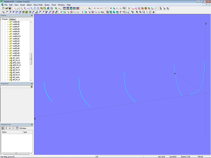
Mold 2, mold 4 and mold 5 (stern)
The plank cross-sections at molds 2 and 4 and at the stern (mold 5) are created in the same way as shown for mold 3. Since a significant number of objects needs to be generated, it is convenient to accomplish this using the Component cl_planks-10.mc2. The parents of this component are the start point of the mold curve, the following mold points and the end point of the mold curve.
For example, let us insert the plank cross-sections for mold 2. First select the start mold point (Ring m2_r0), the inner mold points (Arc-length Rings m2_r1 – m2_r9), and the final mold point (Ring m2_r10). Then, via File/ Component/ Load, select the Component cl_planks-10.mc2, confirm the Resolving Parents dialog with OK, and without further action, the plank cross-sections for mold 2 are created.
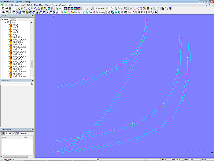
Model clinker-2.ms2 – plank cross-sections at molds 2 to 5
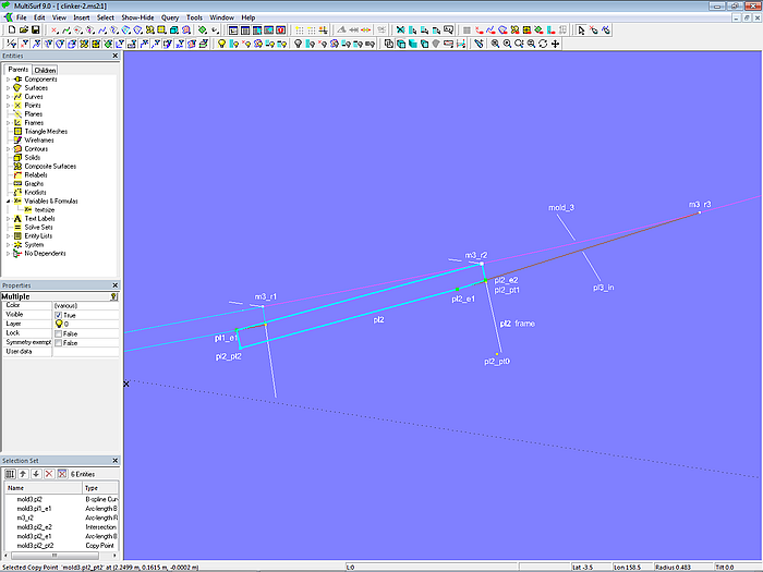
Mold 1 (Bow)
Now we only need the beginning of the planks, their front. At the bow mold, the planks should not overlap, but should run smoothly into the stem rabbet, as in a carvel construction (see illustration in Chapter 1). To achieve this, the landing part of the front must coincide with the back of the plank, creating a step.
Plank 1 - Front
We start with the front of plank 1. It is part of the stem rabbet. Mold_1 is the leading edge (EdgeSnake) of the Offset Surface base_hull_off, the surface of base_hull offset inward by the plank thickness. This curve is also the inner edge of the stem rabbet.
Analogous to the molds already described, on mold_1 lie the Rings m1_r0 (beginning, t = 0) and m1_r10 (end, t = 1) and the inner mold points m1_r1, m1_r2 ... m1_r9 (Arc-length Rings).
For the inner edge of the plank front, the SubSnake mold1_pl1_in is defined using Ring m1_r0 and Arc-length Ring m1_r1. The overlap section between m1_r1 and the Arc-length Ring mold1_pl1_ring is created by the SubSnake mold1_pl1_in_sub. The corresponding point to mold1_pl1_ring on the outer edge of the rabbet (Offset Curve mold1_off) is the Copy Point mold1_pl1_e1 (same t-parameter value). As upper edge of plank 1 and lower edge of plank 2 Line mold1_pl2_bot is spanned between mold1_pl1_ring and mold1_pl1_e1. Finally, the outer edge of the front is SubCurve mold1_pl1_out (with the Control Beads mold1_pl1_e0 and mold1_pl1_e1).
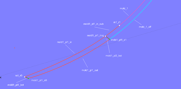
Model clinker-2.ms2 – edge curves of the front of plank 1
This defines all edges of the front of plank 1. The PolyCurve mold1_pl1 combines them into a single curve.
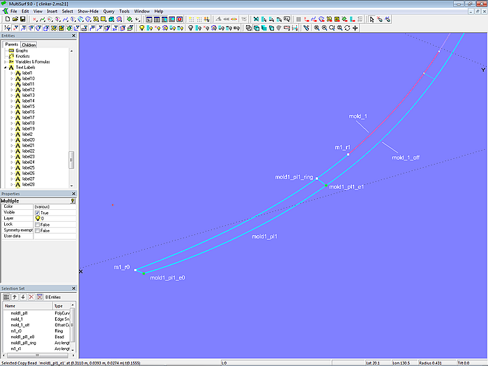
Model clinker-2.ms2 – edges of the front side of plank 1 combined into a single curve
The PolyCurves for the front of the remaining planks 2 to 9 are modeled in the same way. The PolyCurve for the front of plank 10 consists of only 4 component curves.
Model clinker-2.ms2 – plank fronts on mold 1
Model clinker-2.ms2 – master curves for the clinker planks
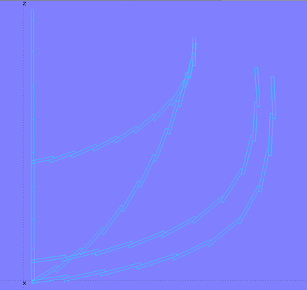
Model clinker-2.ms2 – master curves for the clinker planks
2.4 Planks
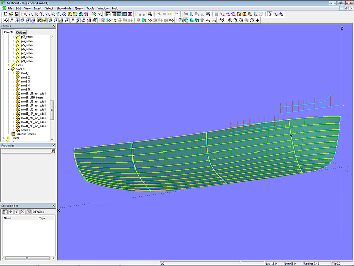
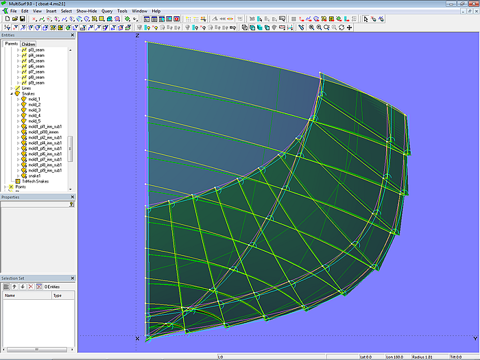
With these plank cross-sections as master curves, the individual planks can now be created as C-spline Lofted Surfaces.
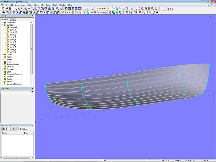
Model clinker-2.ms2 – clinker planks as C-spline Lofted Surfaces

Model clinker-2.ms2 – clinker hull
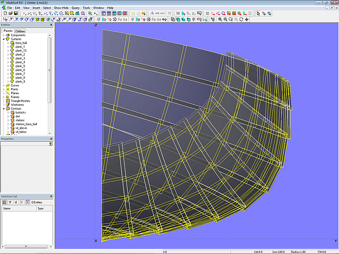
Model clinker-2.ms2 – hull in clinker construction
This is model clinker-2.ms2.
2.5 Hull Surface in Clinker Shape
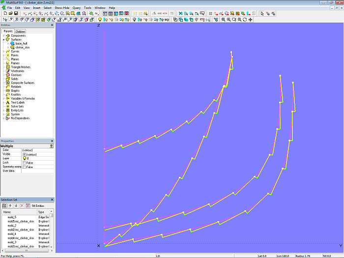
By a selection of points, already determined for the plank cross-sections, master curves can be generated for a single C-spline Lofted Surface that describes the entire outer surface of the clinker hull. In a similar way the inner surface can be determined. This is shown in model clinker-3.ms2.
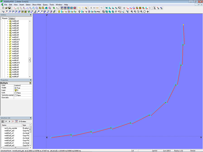
Model clinker-3.ms2 – master curve at mold 3 for the outer surface of the clinker hull
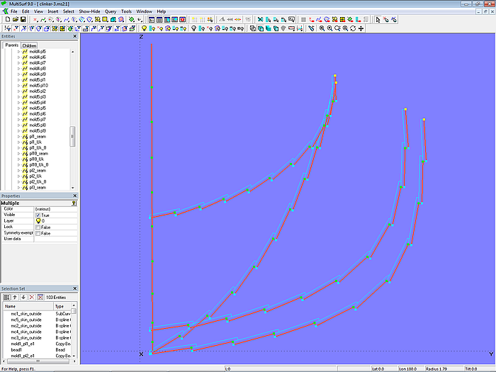
Model clinker-3.ms2 – master curves for the outer surface of the clinker hull
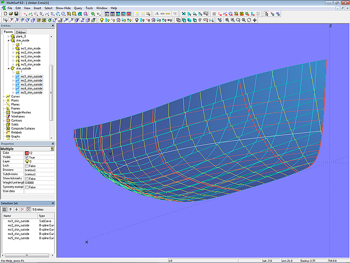
Model clinker-3.ms2 – outer hull side in clinker shape
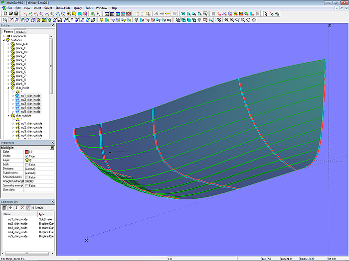
Model clinker-3.ms2 – inner hull side in clinker shape
2.6 Plank Expension
Model clinker-4.ms2 shows how the planks can be flattened. To expand a plank, a Developable Surface is spanned between the longitudinal top edge and the bottom edge of its inside. Let us consider plank 3, for example. The top edge of the inside is the C-spline Curve pl3_seam, which was already defined in Section 2.6, Plank Layout. The bottom edge of the inside is PolyCurve pl3_bot_edge, which consists of the SubSnake mold1_pl3_in (at the rabbet) and the C-spline Curve pl3_bot_edge_0. Using pl3_seam and PolyCurve pl3_bot_edge the Developable Surface plank3_dev is defined.
If plank3_dev were spanned directly between pl3_seam and pl3_bot_edge_0, the expanded shape would show a straight leading edge instead being curved according to the stem shape.
The inside of the other planks are defined as Developable Surfaces in the same way. They can then be flattended using the surface type Expanded Surface.
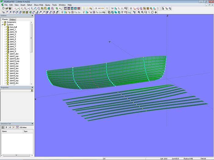
Model clinker-4.ms2 – plank expansion
3 Workboat with Clinker Planking – Advanced
The following describes how Variables and Formulas can be used to make the workboat model described in Chapter 2 more flexible.
3.1 Variables for Plank Thickness and Landing
In Chapter 2, simple assumptions are made: all planks of the workboat have the same thickness (0.010 m), and the landing is 1.7 times the thickness (0.017 m). In the plank cross-section design shown, the values for plank thickness and overlapping width must be specified frequently. Using the entities Variable and Formula for this, these values can be easily changed and are updated accordingly throughout the model.
In model clinker-5a.ms2, the Variable thickness_planks determines the plank thickness. Variable landing_factor specifies the landing factor. The width of the plank landing is calculated by the Formula landing_planks.
3.2 Formulas for Plank Width
With the exception of mold 1 (stem), the plank width was previously calculated by using Tools/ Measure/ Distance to determine the arc-length of the respective mold, divided by the number of planks, and then use this value to place a series of Arc-length Rings as mold points on the mold curve.
In model clinker-5a.ms2 the measurement is replaced by a Formula. Consider mold 3 as an example. Ring m3_r0 is at the beginning of the curve, Ring m3_r10 at the end. The Formula skin_girth_mold3 with the expression: ARCLEN (skin_girth_mold3 / 10, TPOS(m3_r0), TPOS(m3_r10)) calculates the arc length between the two points. Accordingly, the Formulas skin_girth_mold2, skin_girth_mold4, and skin_girth_mold5 determine this measurement for mold 2, mold 4, and mold 5.
Same widths – except for plank 1
To obtain the plank width at the mold, divide the mold length by the number of planks. This width can be determined using another Formula. For example, the Formula breadth_planks_mold3 defines this value using the expression (skin_girth_mold3 / 10). This formula value is then used for the mold points.
If all planks should appear the same width in the external view of the mold, the landing must be added to the plank width for the first mold point. This is done using the Formulas breadth_plank1_mold2 ... breadth_plank1_mold5.
Model clinker-5a.ms2 – flexible plank construction with Variables and Formulas
All planks of the same width
If all mold points are the same distance from each other, plank 1 is narrower from the outside and plank 10 is wider than the other equally wide planks 2 – 9. This is shown in model clinker-5b.ms2.
Model clinker-5b.ms2 – flexible plank construction with Variables and Formulas
Different widths
Equally wide planks on a mold are not a must. Perhaps the top plank should be slightly wider, also the planks in the flat bottom area, but narrower planks would be appropriate in the bilge area. The plank thicknesses can also vary. In this case, we only need a series of additional formulas.
Let us consider model clinker-6.ms2. The 10 hull planks consist of 4 bottom planks, 0.014 m thick, 5 side planks, 0.013 m thick, and the sheer plank, 0.017 m thick. Variable thickness_planks_bottom determines the thickness of the bottom planks, Variable thickness_planks_side determines the thickness of the side planks, and Variable thickness_sheerstrake determines the thickness of the sheer plank. The Variable landing_factor is the factor for the landing, chosen here as 1.8. The Formulas landing_planks_bottom, landing_planks_side, and landing_sheerstrake calculate the respective landing widths of the plank strakes.
Now we need the widths of the bottom planks, the side planks, and the sheer strake.
With
bbottom – width of bottom plank
bside – width of side plank
bsheer – width of sheer strake
G – girth measurement
the following applies:
4 * bbottom + 5 * bside + 1 * bsheer = G
Assuming:
bbottom = 1.25 * bside
bsheer = 1.2 * bside
then follows:
4 * (1.25 * bside) + 5 * bside + 1.2 * bside = 11.2 * bside = G
bside = G / 11.2
The Formulas br_pl_side_mold3 ... br_pl_side_mold5 determine the width of the side planks (5 – 9) at the molds. The Formulas br_pl_bot_mold3 ... br_pl_bot_mold5 calculate the width for the floor planks (1 – 4), and br_pl_sheer_mold3 ... br_pl_sheer_mold5 calculate the width for the sheer strake (plank 10).
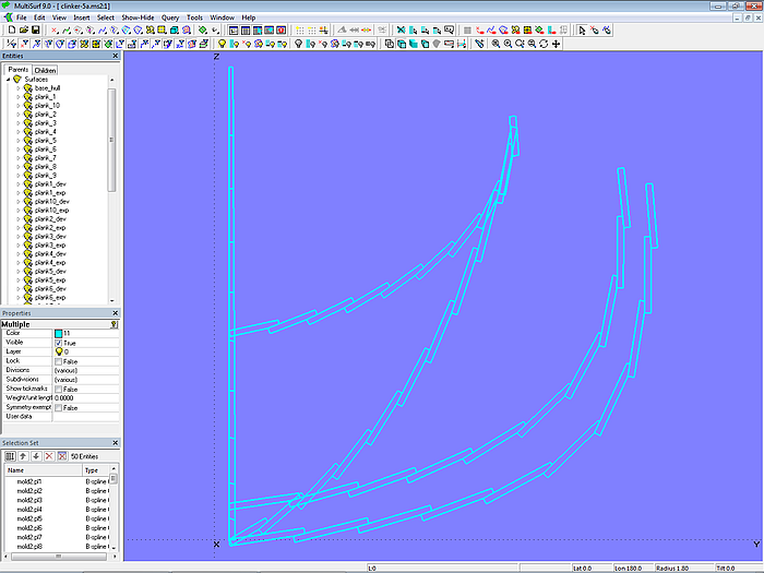
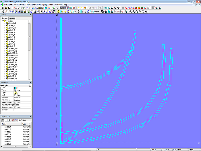
The values of these variables and formulas are then used to define the control points for the plank seams and the plank cross-sections. In the described method, the mold points are therefore not manually positioned; they are derived from the specifications. The points of mold 1 and mold 2 are freely positioned so that the plank seams do not have a distinct inflection point, as in model clinker-1.ms2.
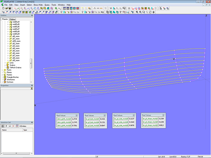
Model clinker-6.ms2 – run of the plank seams and results of calculating the girth length and plank widths of the molds
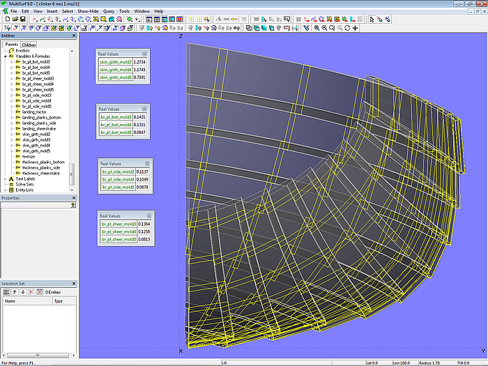
Model clinker-6.ms2 – planks and cross-sections
4 Clinker-skin Method
Chapter 2, Section 2.5 describes how the plank cross-sections at the molds can also be used to create a single outer surface of the clinker hull. However, if the main task is to model a hull surface for a GRP boat that simply resembles clinker construction, the method shown in model clinker_skin-1.ms2 can be used ("clinker look"). It requires much less modeling effort.
With the clinker-skin method, an Intersection Snake is first created for each mold, along with an Offset Curve at a distance equal to the plank thickness. In contrast to the plank cross-section method with molds on the Offset Surface base_hull_off, these molds are Intersection Snakes through base_hull, the base surface of the hull. Mold 1 is the leading edge of base_hull.
Then, equidistant Arc-length Rings on the mold curve are connected to a series of Beads on the Offset Curve to form a zigzag B-spline curve. This, in turn, serves as a support curve for a C-spline Lofted Surface as clinker-like outer surface.
Let us take a closer look at this using mold 3.
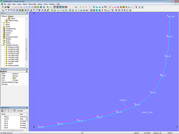
Model clinker_skin-1.ms2 – mold 3 for a clinker-like outer skin
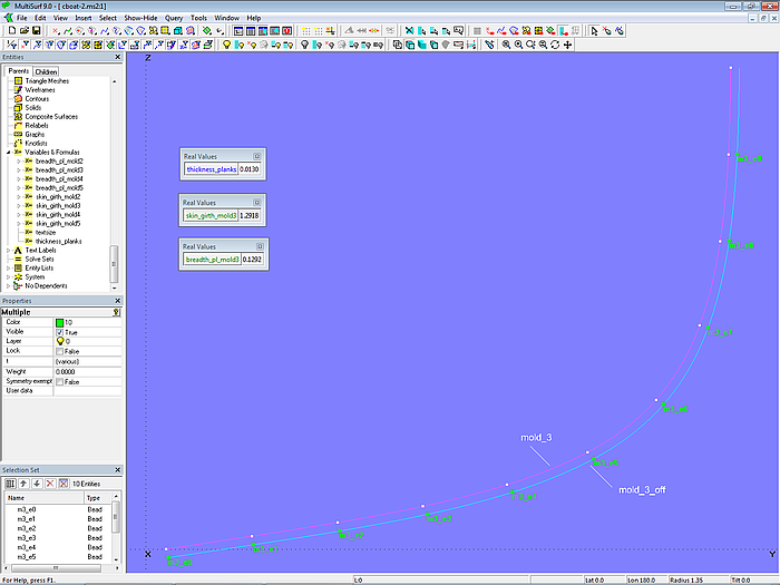
On the Intersection Snake mold_3 the Arc-length Rings m3_r1, m3_r2 ... m3_r8, m3_r9 are located. Their spacing is equal, calculated using the Formula breadth_pl_mold3. On mold_3 the Offset Curve mold_3_off depends; the Variable thickness_planks determines its offset. On mold_3_off the Beads m3_e0, m3_e1, m3_e2 ... m3_e8, m3_e9 are positioned.
Model clinker_skin-1.ms2 – mold 3 for a clinker-like outer skin surface
With these Beads on mold_3_off and the Arc-length Rings on mold_3 as control points, the B-spline Curve mc3_clinker_skin (degree = 1) is defined.
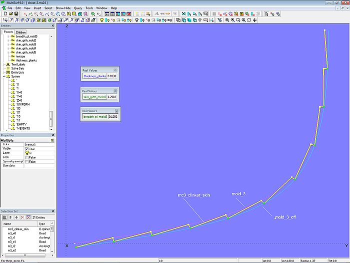
Model clinker_skin-1.ms2 – master curve on mold 3 for a clinker-like outer skin surface
Moving the Beads m3_e1, m3_e2, etc. also changes the curve mc3_clinker_skin. Depending on the position of the beads, the angle spanned for example, between points m3_r1, m3_e1, and m3_r2 can be greater than 90°, or, as with points m3_r3, m3_e3, and m3_r4, less than 90°.
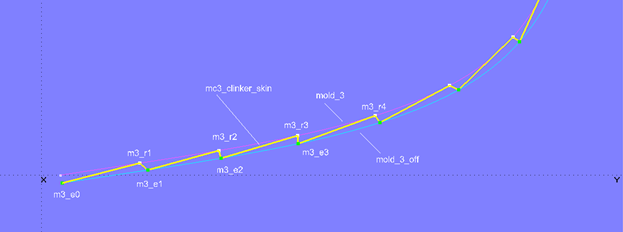
Model clinker_skin-1.ms2 – dependence of the plank steps on the position of the control beads on mold_3_off
The question arises: at what positions must the Beads m3_e1, m3_e2, etc. be located if, for example, the step angle should be 90° everywhere?
To answer this question, a series of semicircles (Arc, Type = 6) are added to the model clinker_skin-1.ms2. Point1 (starting point) is each a mold point on mold_3, Point2 (center point) is the corresponding Bead on mold_3_off, and Point3 is the subsequent mold point. For example, Arc m3_arc1 is created with m3_r1 for Point1, m3_e1 for Point2, and m3_r2 for Point3.
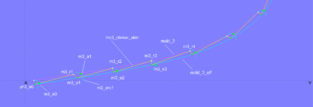
Model clinker_skin-1.ms2 – auxiliary construction for a regular arrangement of the control beads
On semicircle m3_arc0 lies Bead m3_a0. Beads are also located on the other semicircles, but they are Copy Beads (m3_a1, m3_a2, etc.) with m3_a0 as parent. This means, that if on Arc m3_arc0 the Bead m3_a0 is moved, i.e., its parameter t is changed, the Copy Beads on all other semicircles are set to the same t-value.
What does this do for us? Let us set Bead m3_a0 to t = 0.5 and then move m3_e1 on mold_3_off until the B-spline Curve mc3_clinker_skin passes through Copy Bead m3_a1. Strictly now the step angle between the points m3_r1, m3_e1, and m3_r2 is 90°.
Model clinker_skin-1.ms2 – auxiliary construction for equal angles between the plank edges
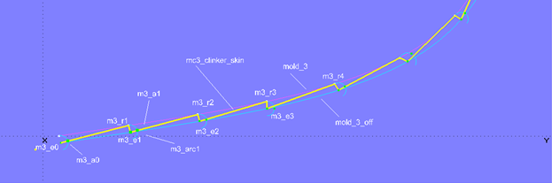
The t-position of a Bead on a semicircle corresponds to an angle between the arc start, the center, and a point on the arc. For t = 1, the angle is 180°; for t = 0.25, the angle is 45°. If the angle should be 95°, the curve point, i.e. our "master" Bead m3_a0, must be set to t = 0.5278 (= 0.5 x 95 / 90).
This gives us reference points for positioning the Beads on the Offset Curve mold_3_off. We need to move m3_e1, m3_e2, etc. so that mc3_clinker_skin runs through our auxiliary points at all times. Then the step angle corresponds to the product of t x 180°.
The Beads are moved manually. With an external program via MultiSurf´s API the arrangement of the Beads can also be automated.
Model clinker_skin-1.ms2 – master curve mc3_clinker_skin on mold 3 with uniform plank steps
This is model clinker_skin-1.ms2. It is used to create the Component cl_skin.mc2. It requires the mold curve (Snake) and the mold points (Rings) as parents; the result is the complete master curve for the outer skin.
In model clinker_skin-2.ms2, this component is used to insert the additional master curves mc2_clinker_skin, mc4_clinker_skin, and mc5_clinker_skin at molds 2, 4, and 5, respectively.
Model clinker_skin-2.ms2 – by Component inserted master curves on mold 2 - mold 5 with uniform plank steps
Now, mc1 for mold_1 on the stem is still missing. It must not run zigzag like the other mcs, since the plank edges should taper off at the stem. Therefore, mc1 is defined by the PolyCurve mc1_clinker_skin. This consists of both the SubSnakes between the Arc-length Rings lying on mold_1 and these Arc-length Rings themselves. It therefore has the same shape as mold_1. Finally, mc1 to mc5 are the supporting curves for the C-spline Lofted Surface clinker_skin.
Why is the EdgeSnake mold_1 not used directly as mc1 for clinker_skin, but rather a complex PolyCurve with the same shape is created? The reason for this is that the parameterization of mc1 must be the same as that of the other mcs. Otherwise, the u-parameter curves of clinker_skin would not map the plank edges, but would start at inappropriate positions.
Model clinker_skin-2.ms2 – clinker-like C-spline Lofted Surface
Model clinker_skin-2.ms2 – clinker-like C-spline Lofted Surface
5 Examples
5.1 Dinghy (plank cross-section method)
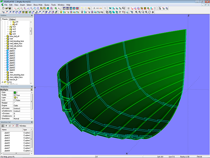
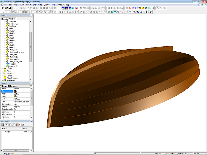
The model dinghy.ms2 shows how to produce a clinker-built dinghy using the plank cross-section method. Stem and keel are also modeled.
The base surface of the 2.40 m long hull is the C-spline Lofted Surface base_hull, supported by five B-spline master curves. Mc1 runs tangentially into the bottom contour. This connection is hard-wired by using Tangent Point p14 as the last but one cp for mc1. Mc5 is a B-spline snake on the transom base surface.
Rabbet
Since stem and keel are also to be modeled in addition to the clinker planking, we need the rabbet on the hull. The rabbet is formed by the abutting surfaces of rabbet front and rabbet side. The outer edge of the rabbet front forms the EdgeSnake stem_rabbet_out at the stem along the leading edge of base_hull. Along the bottom contour this is the EdgeSnake keel_rabbet_out. The inner edge of the rabbet front is formed by the corresponding EdgeSnakes stem_rabbet_in and keel_rabbet_in of the Offset Surface base_hull_off, the hull surface offset inward by the plank thickness.
So far, so good. A closer look at these curves, however, reveals the irregular shape of the inner edge, namely where the two rabbet curves stem_rabbet_in and keel_rabbet_in meet. The Offset Surface base_hull_off also shows this discontinuity.
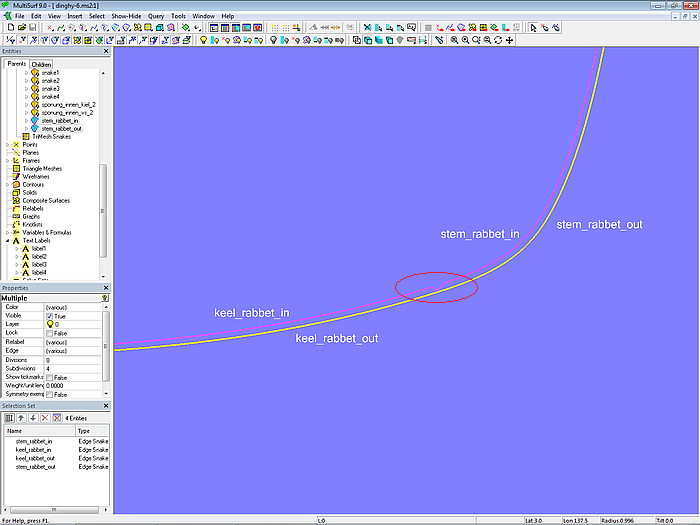
Model dinghy.ms2 – the rabbet curves stem_rabbet_in and keel_rabbet_in meets discontinuously.
To create an Offset Surface, at each point of the base surface defined by its uv-coordinates the tangential plane and its normal must be determined. A point is then determined on this plane at the desired distance.
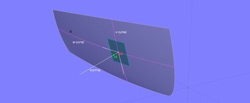
The tangents to the uv-parameter curves define the tangential plane at surface point m0. The surface normal is perpendicular to it.
If two surface edges meet smoothly, the angle between the tangents becomes smaller the closer m0 gets to the connection point.
If two edges of a surface meet tangentially, the angle between the tangents to the parameter curves u_const and v_const corresponding to its uv-coordinates is zero at the connection point. The tangential plane degenerates into a line; a surface normal, and thus an offset surface, does not exist for this point.
At the connection point of the surface edges, the tangent plane degenerates into a line.
Specific to MultiSurf, an Offset Surface is still calculated. However, it shows a break, since the surface normal is only determined up to a limit along the edges at the connection point. Their EdgeSnakes meet each other accordingly discontinuously.
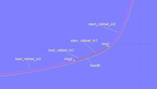
While the two rabbet snakes of base_hull are continuous, the irregular connection of the snakes on the Offset Surface base_hull_off must be corrected. To do this, we put Ring ring1 on the Snake stem_rabbet_in and, depending on it, create the Tangent Point pt5. Similarly, on the Snake keel_rabbet_in, the Ring ring2 is positioned with the Tangent Point pt6 as child. With these four points, the B-spline Curve rabbet_in_fix, which is thus tangentially connected to both rabbet curves, is defined.
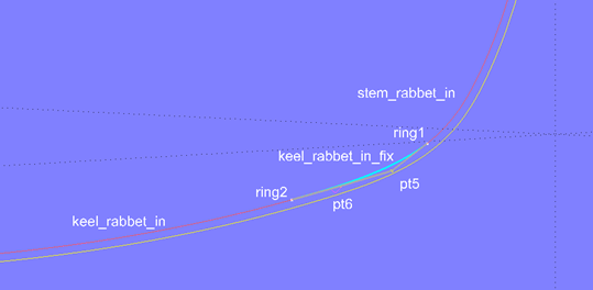
Model dinghy.ms2 – B-spline Curve keel_rabbet_fix bridges the discontinuity between the rabbet curves inside of stem and keel.
This curve is then divided into the SubCurves stem_rabbet_in1 and keel_rabbet_in1 using Bead bead6. The curve section on stem_rabbet_in starting at ring1 is SubSnake stem_rabbet_in2. Similarly, SubSnake keel_rabbet_in2 defines the curve section from ring2 to the end of keel_rabbet_in along the keel. Finally, these curve sections are combined to form the PolyCurves stem_rabbet_in_fixed and keel_rabbet_in_fixed.
Model dinghy.ms2 – components of the PolyCurves stem_rabbet_in_fixed and keel_rabbet_in_fixed
By shifting the cps of the B-spline Curve rabbet_in_fix, it must be ensured that the inner edge of the keel and stem rabbets run harmoniously with the outer edge.
Model dinghy.ms2 – surfaces of the rabbet front at stem and keel
Plank Layout
The dinghy is to be constructed with 9 planks, each 8 mm thick, across 7 molds. The width of the top plank is to be 0.120 m at mold 4. The width at the remaining molds is calculated by a formula in the ratio of the respective girth to the girth of mold 4. The mold points (Arc-length Rings) for the width of plank 1 are freely positioned. The same applies to the mold points at mold 2. On the remaining molds, the Arc-length Rings for the mold points are arranged using formulas so that planks 2 to 8 are each of the same width.
Model dinghy.ms2 – plank seam layout
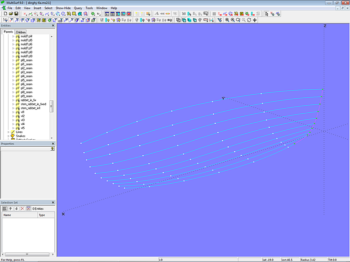
Planks
The planks for the model dinghy.ms2 are modeled in accordance with the plank design for the workboat. Each plank is supported by seven cross-sectional master curves.
Model dinghy.ms2 – planks and master curves
Stem
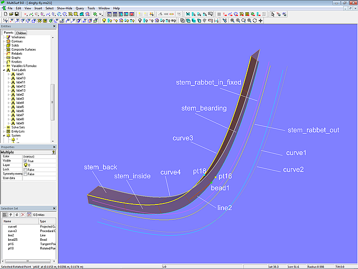
The curves for the outer and inner edges of the rabbet front have already been created for the stem. These are the PolyCurve stem_rabbet_in_fixed and EdgeSnake stem_rabbet_out. We still need the stem front, the outer stem side, the rabbet side, the inner stem side, and the rear of the stem.
We start with the outer side of the stem. The stand-out to the leading edge of the planking (EdgeSnake stem_rabbet_out) should be 20 mm at the top and 30 mm at the bottom. The half width should be 10 mm. Corresponding to the bow master curve mc1, the B-spline Curve curve1, controlled with cps, is inserted with a similar shape. This curve is then projected onto the midship plane (*Y=0) as Projected Curve curve2. The Ruled Surface stem_front is spanned between curve1 and curve2, and the Ruled Surface stem_outside is spanned between curve1 and stem_rabbet_out.
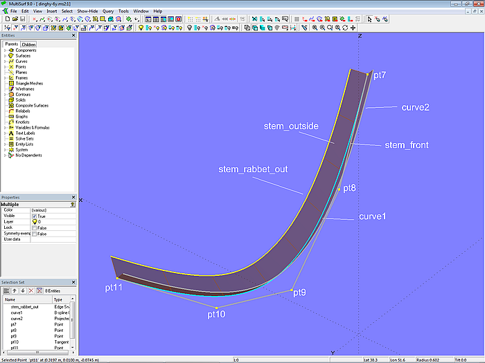
Model dinghy.ms2 – construction of the outer edges of the stem
With their inner sides, the planks rest on the stem at the rabbet side. This surface is modeled in the following steps. The edge of the rabbet side that is common to the rabbet front is the PolyCurve stem_rabbet_in_fixed. To produce the outer edge of the rabbet side, the Ring ring3 and its dependent Tangent Point pt12 lie on the EdgeSnake stem_rabbet_out. Both points determine Line line1. Offset Point pt13 is also dependent on ring3. This point is rotated 90° around line1 using the Rotated Point pt14. This, in turn, is then projected onto the base surface base_hull as Projected Magnet m6. In the Procedural Snake snake1 this construction of m6 is repeated for all positions of ring3. Finally, snake1 is offset inward by the plank thickness using the Offset Curve stem_bearding.
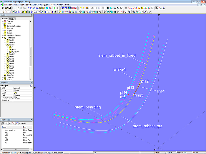
Model dinghy.ms2 – construction of the rabbet edges
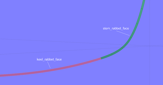
This creates a rabbet side of constant width, spanned by the Ruled Surface stem_bearding_face between the curve stem_bearding and the curve stem_rabbet_in_fixed.
The rabbet front forms the Ruled Surface stem_rabbet_face between the curve stem_rabbet_out and the curve stem_rabbet_in_fixed.
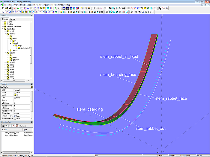
Model dinghy.ms2 – front and side of the rabbet on the stem
For the inner part of the stem beam the curves, that define its height and width, are still missing. A procedural construction is used to achieve a constant height and width of the back. To do this, the Bead bead1 is set on the Offset Curve stem_bearding. The Tangent Point pt16 depends on this; its offset value determines the inside height of the stem. On bead1 also depends Point pt17; Line line2 runs between both points. Pt16 is now rotated 90° around line2 by the Rotated Point pt18. For all t-values of bead1 this construction is repeated by the Procedural Curve curve3. Its projection to *Y=0 (midship plane) is Projected Curve curve4.
The inside of the stem is now the Ruled Surface stem_inside between the curve stem_bearding and curve3. The back of the stem is the Ruled Surface stem_back between curve3 and curve4.
Model dinghy.ms2 – inner surfaces of the stem
So far for the construction of the individual stem surfaces and their edges.
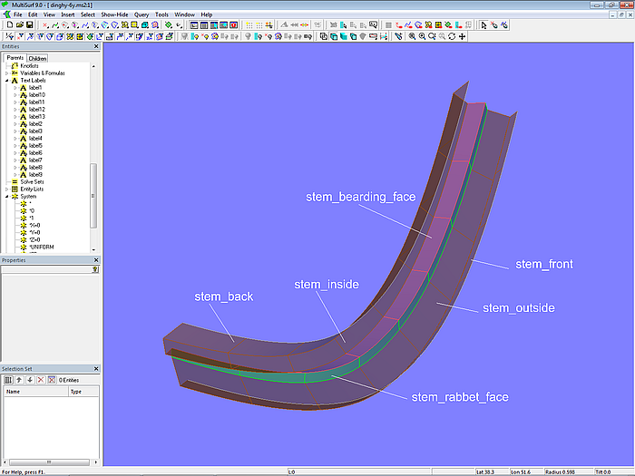
Model dinghy.ms2 – surfaces of the stem
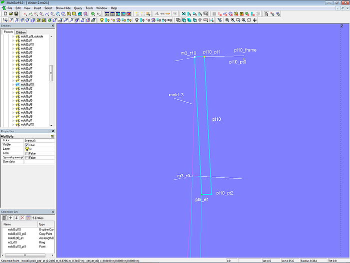
Keel
The keel beam consists of as many individual surfaces as the stem. The rabbet surfaces have the same constant width as at the stem. The height and width of the inner and outer keels are variable.
The rabbet front for the keel was already generated when correcting the inner edge of the rabbet. The construction of the rabbet side is essentially the same as that for the stem. Ring ring4 lies on the EdgeSnake keel_rabbet_out, and the Tangent Point pt19 depends on it. Both points define Line line3. Relative to ring4 is Offset Point pt20; its offset value determines the width of the rabbet side. Pt20 is rotated 90° around line3 by the Rotated Point pt21, which is then projected onto the base surface of the hull base_hull by the Projected Magnet m7. This construction of a surface curve with a constant distance from its reference curve is accomplished by the Procedural Snake snake2. The Offset Curve keel_bearding, in turn, depends on snake2. The bearding face is the Ruled Surface keel_bearding_face between the curves keel_rabbet_in_fixed and keel_bearding.
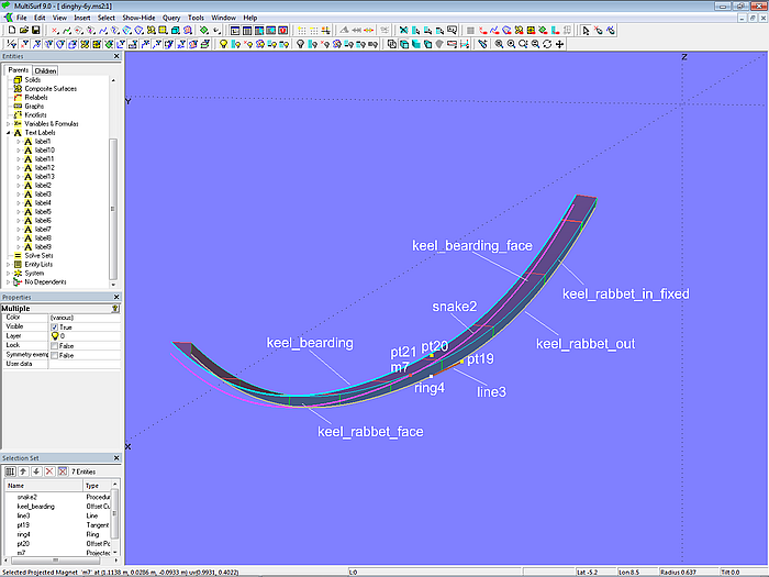
Model dinghy.ms2 – construction of the bearding face of the keel
Width and height of the inner keel are determined by the C-spline Curve curve5. The inner keel side is the Ruled Surface keel_side_in between keel_bearding and curve5. The Ruled Surface keel_top runs between curve5 and its projection curve6 onto the *Y=0 plane.
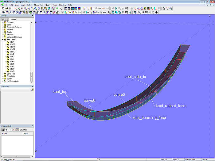
Model dinghy.ms2 – construction of the inner sides of the keel
Width and depth of the outer keel are determined by the C-spline Curve curve7. This is projected onto *Y=0 as curve8. The keel side is the Ruled Surface keel_side between keel_rabbet_out and curve7. The keel bottom is the Ruled Surface keel_bottom between curve7 and curve8.
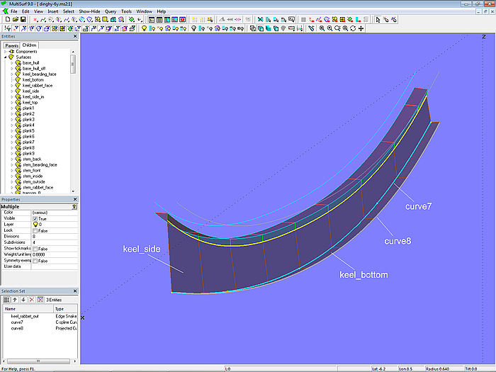
Model dinghy.ms2 – construction of the outer keel
Model dinghy.ms2 – construction of stem and keel
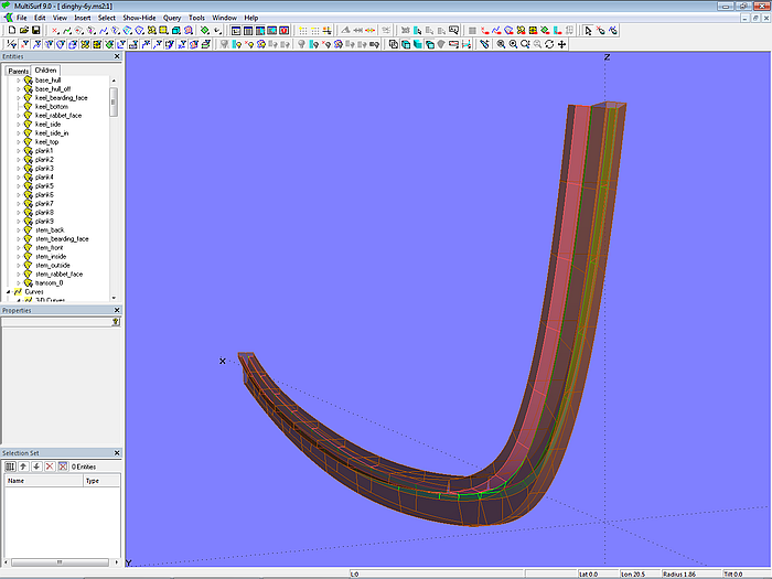
Model dinghy.ms2 – construction of stem and keel
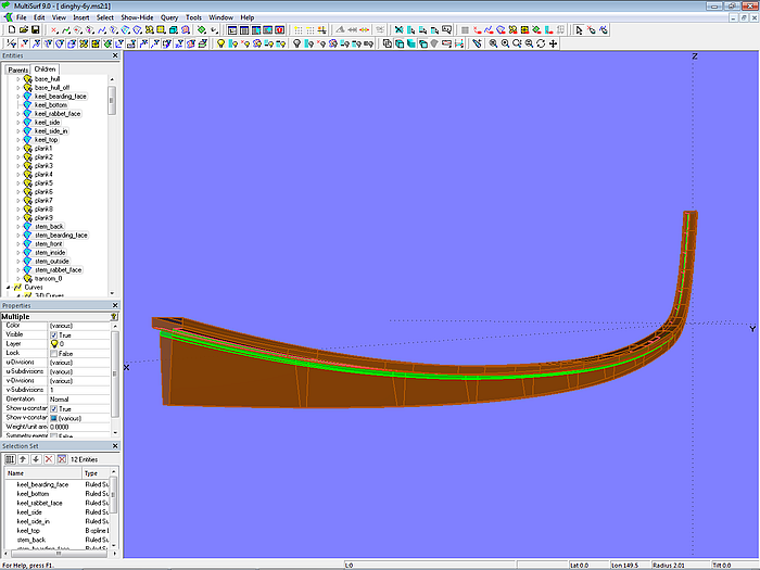
Model dinghy.ms2 – clinker hull with stem and keel
Model dinghy.ms2 – clinker hull with stem and keel
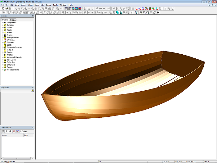
Model dinghy.ms2 – clinker hull with stem and keel
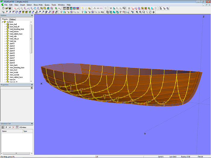
So much for the geometrie of the model dinghy.ms2.
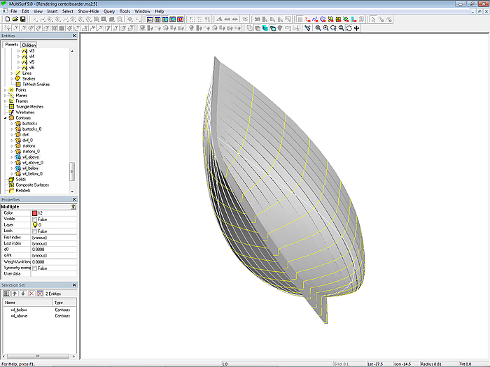
5.2 Sailboat (clinker-skin method)
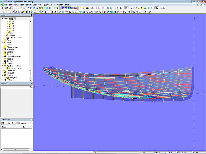
Model centerboarder.ms2 shows a 7 m long centerboard sailboat with a "clinker look." The clinker-skin method is used for the hull definition. The starting point is the C-spline Lofted Surface base_hull, defined with 7 B-spline mcs with 7 cps each. The C-spline Lofted Surface clinker_skin, which looks like a clinker construction, mimics a hull with 12 planks. Except for the top plank, all planks have the same width at each mold.
The C-spline Lofted Surface clinker_skin is supported by 7 mold curves. The Component cl_skin_12planks.mc2 is used for this purpose. To apply it, first select the mold points of the mold in question, then choose the Component via File/ Component/ Load, confirm the Resolving Parents dialog with OK, and the zigzag B-spline master curve for the mold is generated.
Please note, that the plank overlap vanishs also at the stern.
Model centerboarder.ms2 – sailboat hull in "clinker look"
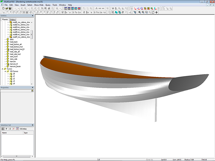
Model centerboarder.ms2 – sailboat hull in "clinker look"
Model centerboarder.ms2 – sailboat hull in "clinker look"
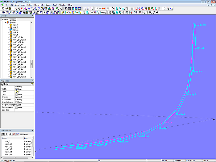
Appendix 1 – Surface Model Based on Diagonal Section Offsets
Template: offsets of diagonal sections
Model diagonal_plan.ms2 shows the diagonal frame structure underlying the measurements. Arc-length Beads are used to position section points along the diagonal lines. Corresponding section points are interpolated by C-spline Curves in both longitudinal and transverse direction. The model is scaled in the X direction so that its length is 5 m.
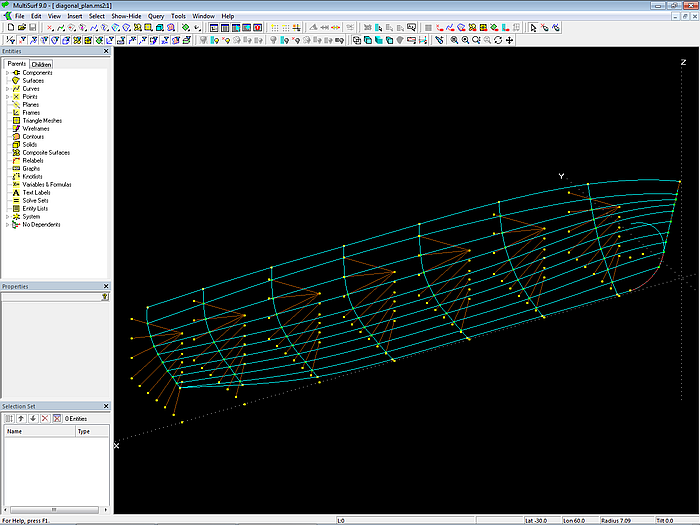
Model diagonal_plan.ms2 – C-spline Curves interpolate section points in longitudinal and transverse direction.
3DA wireframe file
From the model diagonal_plan.ms2 the curves of stem, frames and transom are saved in the 3DA wireframe file pattern.3da (File/ Export 3D/ 3DA wireframe).
From the information in the offset table we have now converted the shape of frames, stem and transom into a numerical form.
Surface Fitting
The 3DA file pattern.3da is the template for the creation of the actual round-bilged hull surface. To do this, create a new model, save it with the file name clinker-0.ms2, and insert the 3DA file pattern.3da via Insert/ Wireframe.
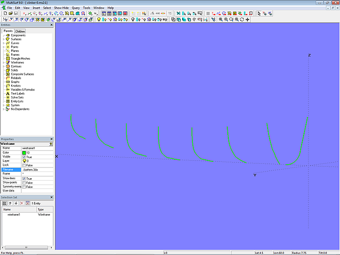
Model clinker-0.ms2 –wireframe file pattern.3a, imported as a template, was saved in the model diagonal_plan.ms2.
Now, B-spline Curves (degree = 3) with 5 cps each are created for the wireframe curves. It is very convenient to use for this purpose the function B-spline Curve Fit via Tools/ Special – control points and curves are generated in one go.
The stem and four stations are selected as master curves for the round-bilged form of the workboat. The C-spline Curves vl_1 to vl_5 pass through corresponding cps to serve as guide curves for fairing.
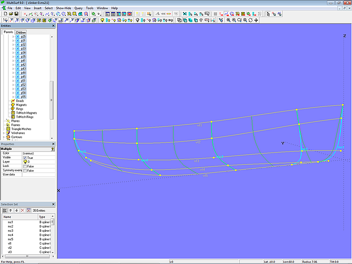
Model clinker-0.ms2 – master curves (B-spline curves), control points, and guide curves for fairing (C-spline curves)
The stem mc (mc1) and stern mc (mc6) deviate slightly from the template. This allows the keel area aft to be slightly larger, and the stem curvature is more even. The last two cps of mc2 are shifted a bit aft and outward relative to the cps of mc1. C-spline Curves tend to oscillate if their cps are close together.
The C-spline Lofted Surface base_hull is now supported by mc1 to mc6. This, in turn, is intersected by Contours to display stations, waterlines, buttocks. By moving the cps of the mcs the hull surface is then faired.

Model clinker-0.ms2 – base hull surface of the workboat
So much for the base surface of the workboat. However, there are no clinker planks to be seen anywhere in the model clinker_0.ms2. Therefore, from here, back to Chapter 2, Section 2.1, Base Hull.
Appendix 2 – Graphical Representation of Plank Width
Model diagram_10planks.ms2 shows how to create a diagram that represents the change in the width of 10 planks over the length of the mold. Starting point as mold is Intersection Snake m2, on which the mold points m2_r0, m2_r1 ... m2_r9, m2_r10 lie. The curved mold is then flattened into the straight curve exp using the curve type Expanded Curve. Using the Copy Beads e1, e2 ... e9, e10 the t-position of the mold points on m2 is transferred to the Expanded Curve exp. The vertical Lines l1, l2 ... l9, l10 are then created at these curve points.
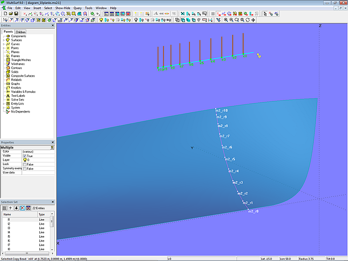
Model diagram_10planks.ms2 – graph display for plank width
The plank width must now be plotted along the respective line. Let us take the width of plank 1 as an example, i.e., the distance between points m2_r0 and m2_r1. In step 1, this distance is copied to the base point e1 of Line l1 using the Copy Point p1_0. Then, in step 2, Line l1 is intersected in the Intersection Bead d_pl1; as its parents e1 is used for Mirror/surface and p1_0 for Point. What does this mean? Since Mirror/surface is a point, the intersecting object for l1 is a sphere with center e1 and a radius equal to the distance e1 – p1_0.
In a similar way the other plank widths are entered in the diagram. Finally, the Intersection Beads d_pl1, d_pl2 ... d_pl9, d_pl10 are connected by a B-spline Curve of Degree = 1.
This creates a graph that shows the plank width versus the mold length.
If the position of the mold points is changed, the graph changes accordingly. This provides a tool for fairing the run of the planks.
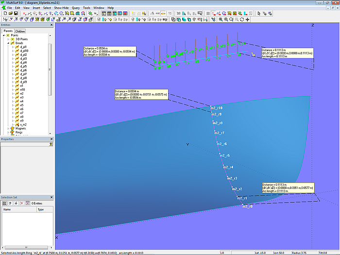
Model diagram_10planks.ms2 – plank width diagram
Component
To use the diagram, for example, in model clinker-1_final.ms2, the Component diagram_10planks.mc2 is created using the two Entity Lists parents and products and the "selectforcomponent" Command via File/ Component/ Save.
======================================================================================